

i2c Front Panel
Switching from individual full-size PINE64 boards to the Clusterboard necessitates a change to the electronics for RAIN-PSC’s front panel. The original plan was to use GPIO pins on each board to directly interface with the LED’s and switches on the panel, but the Clusterboard exposes far fewer pins for each compute module, so another approach is required. 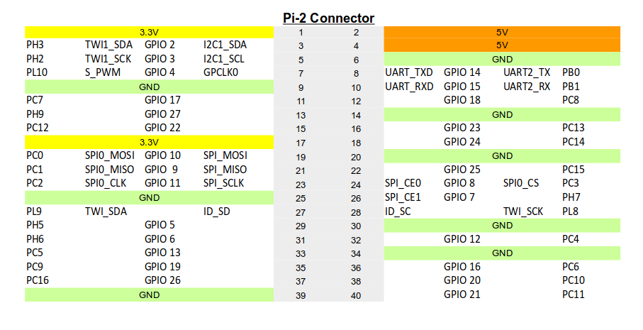
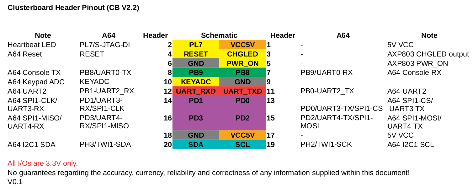 On the schematic, one i2c bus is exposed for each compute module. This looked promising so I dug into using i2c to interface with a chip that could drive the panel LED’s and read input from the panel switches. I settled on the MPC23017 port expander. This chip is probably overkill for the application (it has a lot more I/O’s than I need) but I was able to find a fair amount of documentation on using it, and I can always switch to something more compact once I know more about exactly what I need. Since I’m waiting for the Clusterboard to arrive, I started working on getting this working with a full-size PINE64. This took a bit of experimentation and I was hampered by the fact that I couldn’t tell for sure if any of the pieces (computer, operating system, electronics, etc.) were correctly setup on their own. Holding more than one “variable” when troubleshooting is a rookie mistake, but since this is the first time I’ve really worked with i2c I didn’t have much in the way of “constants” available in the lab to narrow things down. After tearing things apart and starting-over a few times I was able to identify primary source of the trouble.
 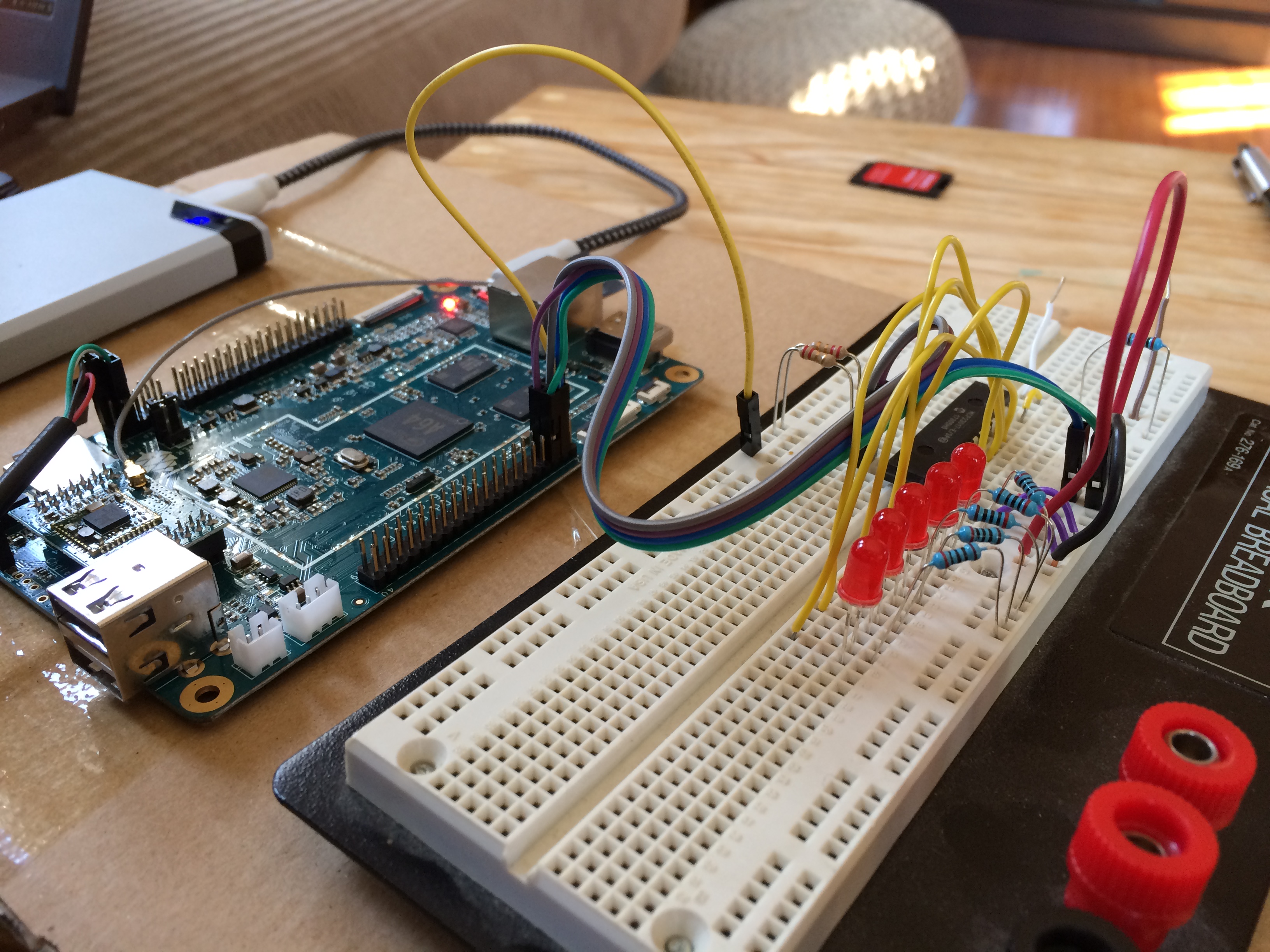 In order for Linux to properly detect devices attached to the i2c bus, it is necessary to “pull-up” the SDA and SCL lines. These pins on the PINE64 include built-in resistors, but the value of these resistors is too high to work correctly in this case. That means it’s necessary to add resistors externally to tie pins 3 (SDA) and 5 (SCL) to pin 1 (3.3v) on the PI-2 connector. I learned this after sifting through a thread on the PINE64 forum about interfacing the PINE64 with an i2c-based Adafruit LCD module. [caption id=“attachment_5108” align=“aligncenter” width=“2448”]
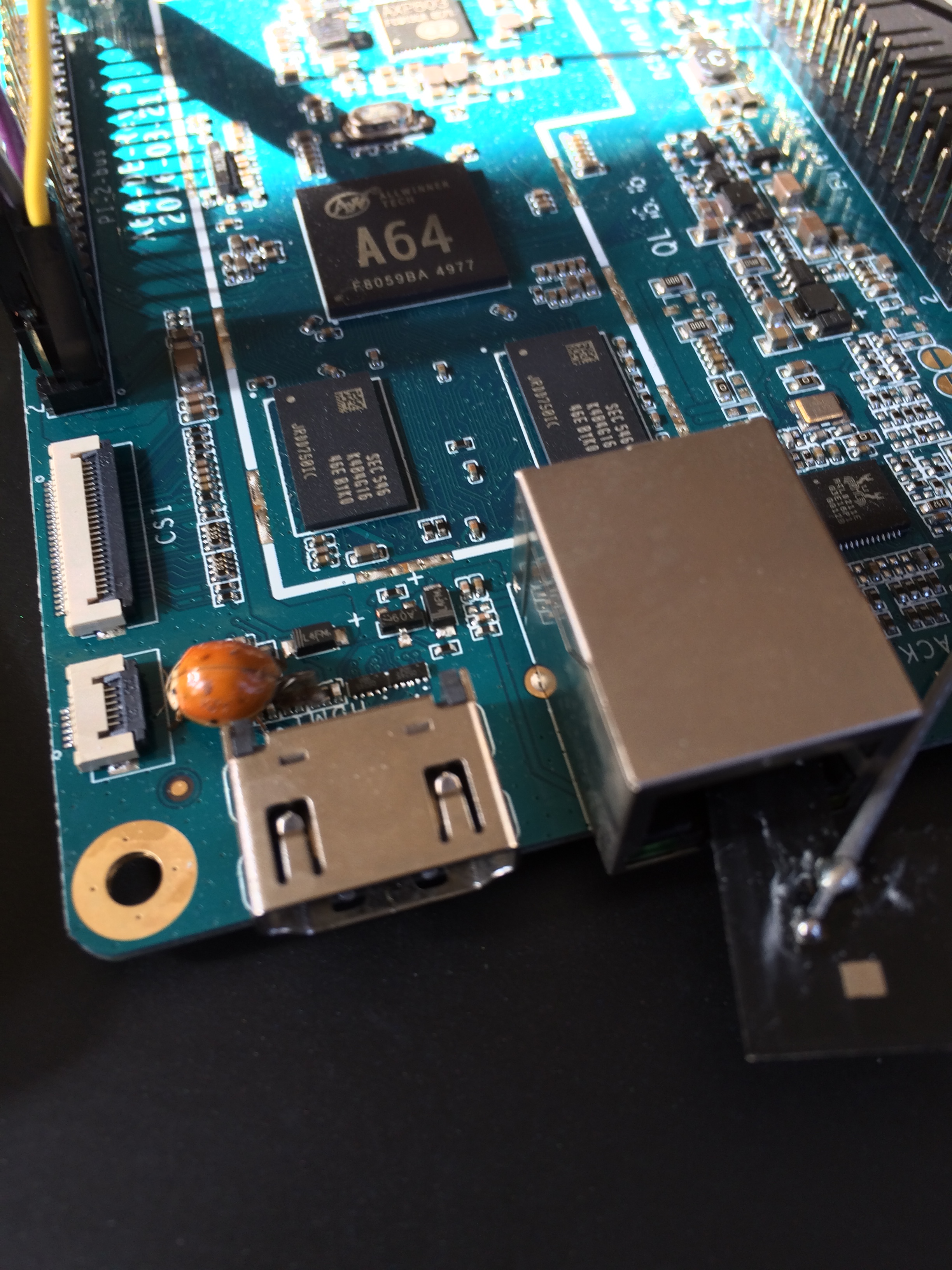 Unfortunately, this wasn’t the only bug[/caption] However in my case the problem was with the value of these resistors. Based on what I had read the target value should be around 2k. I went with 2.2k because that’s what I had on-hand, and figured this was close enough. It was not After eliminating everything else I could think of, I tried a pair of 200(k?) resistors (the same ones that I was using to limit current to the LED’s) and viola, it started working!
 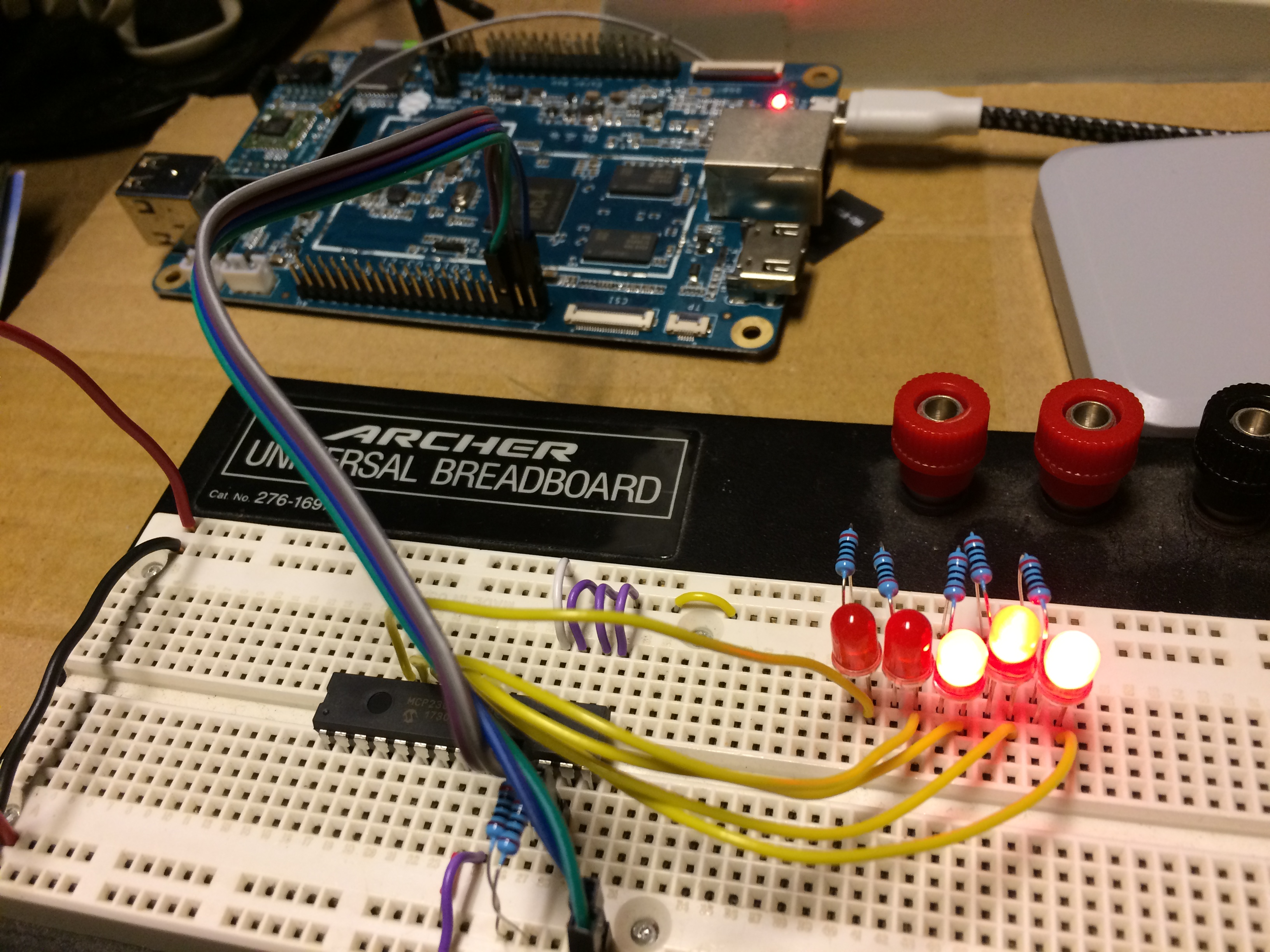 This is far from the first time that I’ve been bitten by some basic electronics problem, and had I spent more time learning about the parts I was working with (schematics for the PINE64, datasheet for the MPC23017, etc.) I may have gotten it right in the first place. However, if I did this for everything I worked on my projects would take exponentially longer, and I’d get a lot less done. You could argue that doing things this way takes longer (due to spending time chasing avoidable mistakes) but this has the added side-effect of improving my troubleshooting skills, which have a much broader application than memorizing the technical details of specific components. That’s not to say one approach is superior to the other. I think this approach comes natural to me and working this way preserves my flow and gumption, but I can see how it would be the opposite for someone else. This might be part of the reason I’m better at software than hardware, even though I think one is as fun as the other. Now that the hardware is in order, I’ll dive into writing the software to do something useful with all this next time.
References
- http://files.pine64.org/doc/Pine%20A64%20Schematic/Pine%20A64%20Pin%20Assignment%20160215.pdf
- http://raspberrypi.link-tech.de/doku.php?id=mcp23017
- https://forum.pine64.org/showthread.php?tid=2079&page=2
- https://www.raspberrypi-spy.co.uk/2013/07/how-to-use-a-mcp23017-i2c-port-expander-with-the-raspberry-pi-part-1/
- https://forum.pine64.org/showthread.php?tid=2948
- https://gist.github.com/pfeerick/fe8ebd68623d6d775e7b654aa32ec6fa
- https://forum.pine64.org/attachment.php?aid=1111
Comments
Jason J. Gullickson: Thanks for the suggestion pfeerick, I will check that chip out! It’s cool to hear from another Clusterboard user. My original design used regular PINE A64 boards and more of a custom interconnect, but then the Clusterboard came along. It’s not as flexible as my original design, but it saves a ton of time and space and just happened to fit inside the case I had already selected for this phase of the project. I’m looking forward to spending more time on the software/application side of the work once I get the hardware to a point where I can fit it all back inside the box :)
pfeerick: If you want a smaller I2C expander, have a look at the MCP23008… it’s the smaller 8 I/O cousin of the MCP23017 and should work just as readily. I’ve just come across your blog, and will be eagerly following it as you’re doing much the same as I want to do with a clusterboard… I have the board and all the nodes… just need to put it to use!
Peter Feerick: If you want a smaller I2C expander, have a look at the MCP23008… it’s the smaller 8 I/O cousin of the MCP23017 and should work just as readily. I’ve just come across your blog, and will be eagerly following it as you’re doing much the same as I want to do with a clusterboard… I have the board and all the nodes… just need to put it to use!