

Spent some time researching and documenting everything I could find about the on the SolarHome 620.
Battery
BioLite publishes the following battery details on their website:
- 3300mAh
- 6.5 VDC
- 20 Wh
- LiFEPO4 chemistry
Based on this I believe that the battery is a pair of 26650 cells, perhaps simular to this: https://www.batteryspace.com/custom-lifepo4-26650-battery-6-4v-3300mah-s-s-21wh-3-5a-rate.aspx
Inputs & Outputs
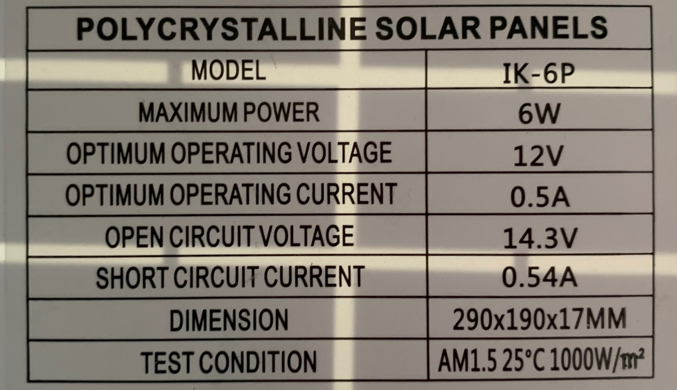
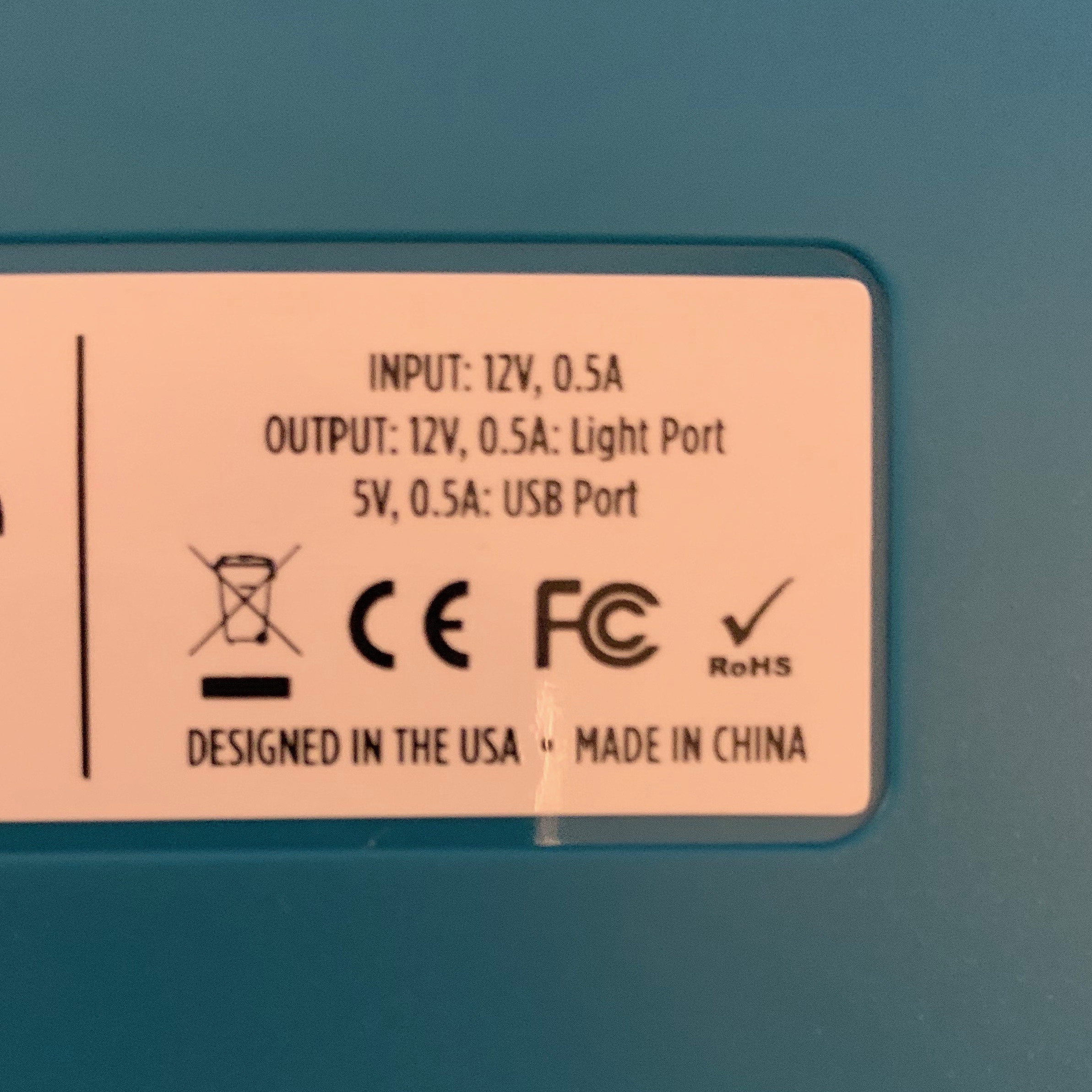
I also spent some time probing the inputs and outputs. Between the documentation and the lables on the hardware you can find a number of useful details:
| Count | Description | Connector | Volts DC | Amps |
|---|---|---|---|---|
| 1 | Solar panel input | 4.8mm barrel | 12 | 0.5 |
| 2 | Lamp output | 5.5mm barrel | 12 | 0.5 |
| 2 | USB charger | USB A-Type | 5 | 0.5 |
| 1 | Expansion battery | Female Mini DIN-4 | ? | ? |
Power In
Knowing the power input parameters is exciting because one of the most common complaints I see online about the SolarHome is that there’s no way to charge the battery other than using the solar panel. This isn’t a big deal if you’re installing the system somewhere for awhile where it can get charged-up, but if you’re going camping or something more temporary, it would be nice to head-out with a full battery in case you don’t have a full day of sunlight ahead of you.
It also opens up the possibility of using other off-grid power sources such as wind or micro-micro-hydro. Without knowing how much regulation capacity the SolarHome provides, it would be prudent to have regulation on the supply-side of any alternative power source you come up with, but so long as you don’t push more than 12VDC @ 0.5A into the unit, you shouldn’t be in any more danger than you would be using the supplied solar panel.
Power Out
My guess is that the USB charging ports will be the best way to get power out of this unit. Since they are designed to charge unknown devices they should have ample regulation to prevent you from harming the device.
12VDC is avaliable via the jacks intended for the lamps which ship with the system, but it’s less clear how the control unit interacts with devices connected to these outputs, so you may experience unexpected fluctuations in power from these ports. In addition, since these ports are intended specifically for the lamps provided by BioLite it’s possible that they don’t have any regulation. If you were to connect a load that draws more current than the ports are designed to deliver (0.5 amps) you may damage the system.
Unless you can be sure to only draw 0.5A or less, it’s best to avoid using these for now.
Mysterious Expansion Port
BioLite doesn’t provide any additional information about the “Expansion battery” port other than that it’s used to connect additional batteries and that I can’t buy one. I started poking-around at the port to see what it does and here’s my best-guesses so far:

Pins are numbered counter-clockwise starting with the lower-right pin.
| Pin | Measurement | Purpose |
|---|---|---|
| Skirt | 0 VDC | Ground |
| 1 | 0 VDC | Serial RX |
| 2 | 3.3 VDC, fluctuating | Serial TX |
| 3 | 12 VDC | Power to charge external battery |
| 4 | Floating | Not connected |
The only connections I’m sure of are the skirt (ground) and pin 3 (12VDC). At first I thought pin 4 was another ground but after seeing a signal on pin 2, I think it might be the receiving pin for a 3.3v serial connection (given the proximity to pin 2).
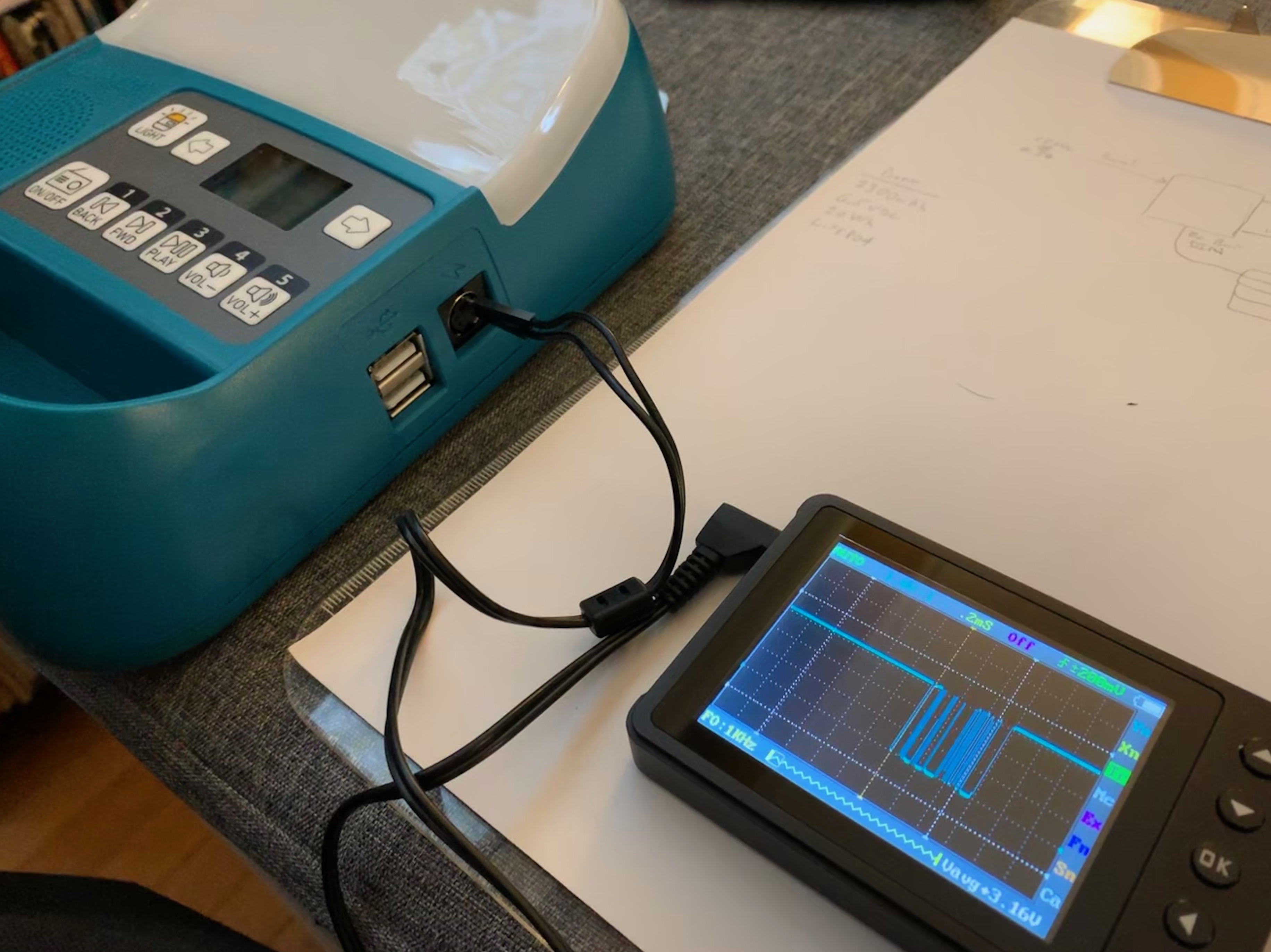
When the control box is idle pin 2 is at 0 volts. If a button is pressed, pin 2 goes high to 3.3v. With the oscilloscope connected there appears to be a signal transmitted on pin 2 which appears as a series of voltage drops. This sequence repeats about once ever 5 seconds as long as the LCD is displaying information.
It may be possible to learn more about this signal using only an oscilloscope, but if my scope can do it, I don’t know how to use it that way. I did a little searching on reverse-engineering serial signals and landed on using a logic analyzer as the next step in decoding this signal. I’ve never used a logic analyzer before, but I was able to find a USB-based device for about $12 that is compatible with the open-source Sigrok software, so I decided to give it a go.
Based on the above my guess as to how this works is that the external battery communicates with the control box using a serial command protocol to share state-of-charge information. This data is then used by the control box to display capacity information to the user via the LCD. I’m not sure why the battery charge voltage is 12VDC vs. something closer to typical LiFEPO4 charging voltage (around 3.5VDC), my only guess is that they are using the same charging circuit design in the expansion battery that they are using in the control box (which uses a 12VDC supply as well). Since there appears to be 12VDC on pin 3 all the time (even when there is no power coming from the solar panel and the LCD is turned off), my guess is that it’s up to the expansion battery to decide how much to draw from the control unit and that this is negotiated via serial communication.
That said these are all guesses. I haven’t done enough of this type of signal analysis to have much confidence in my findings so don’t go out using these pins assuming I know what I’m talking about. Hopefully I’ll be able to confirm some of this after the logic analyzer arrives (and I learn how to use it).