

Fits and Starts
I redesigned the 3d printed parts of the compute module so they can be printed within the build envelope of the Monoprice Mini Delta (I really need to write a review of that printer sometime). The reason for this is that I need to iterate on these modules faster and due to it being winter the ambient temp in the lab makes it hard to print things this large and flat on my Reprap without curling. 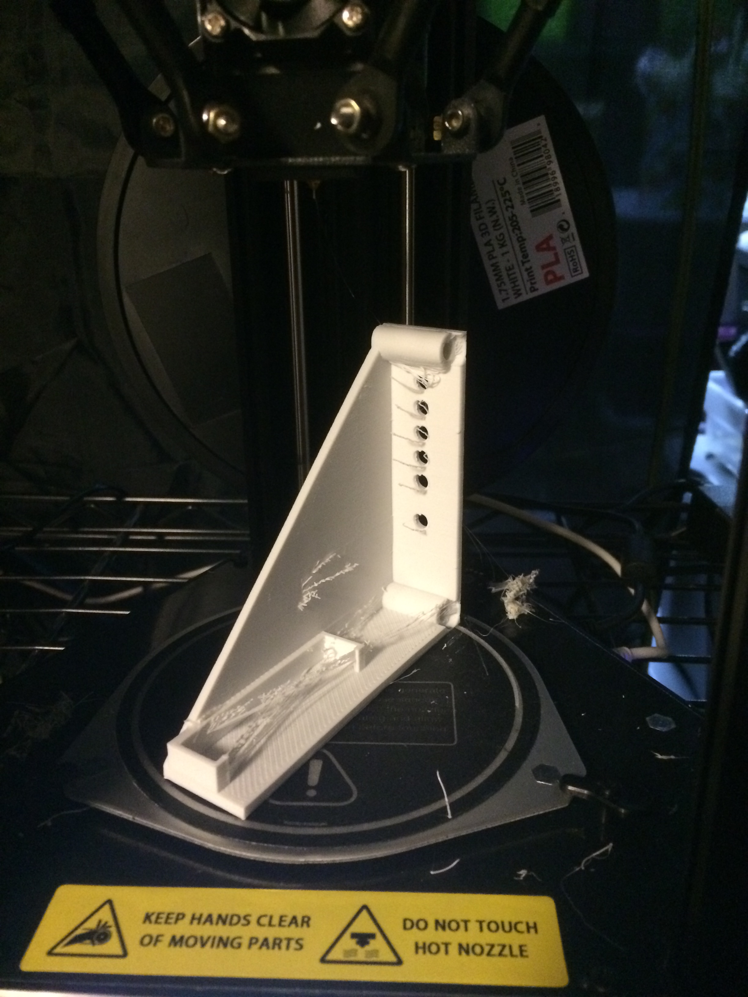 I did some test fitting with the new modules and ran into a couple of problems that necessitate some changes to both the modules and the front panel design. Due to Ethernet switch interference, about 40mm of room on the front panel for module brackets is lost. Based on initial layout tests, this gap falls on the right-hand side of the chassis. Because of this, I can only fit 7 modules at the current module size (25mm).
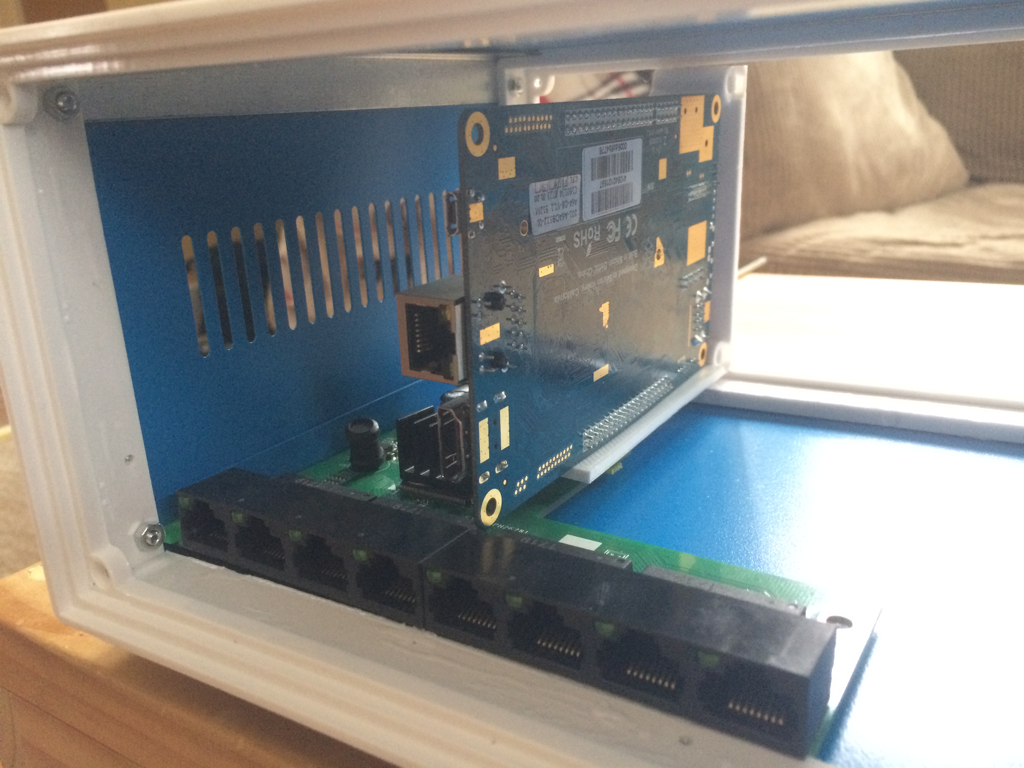
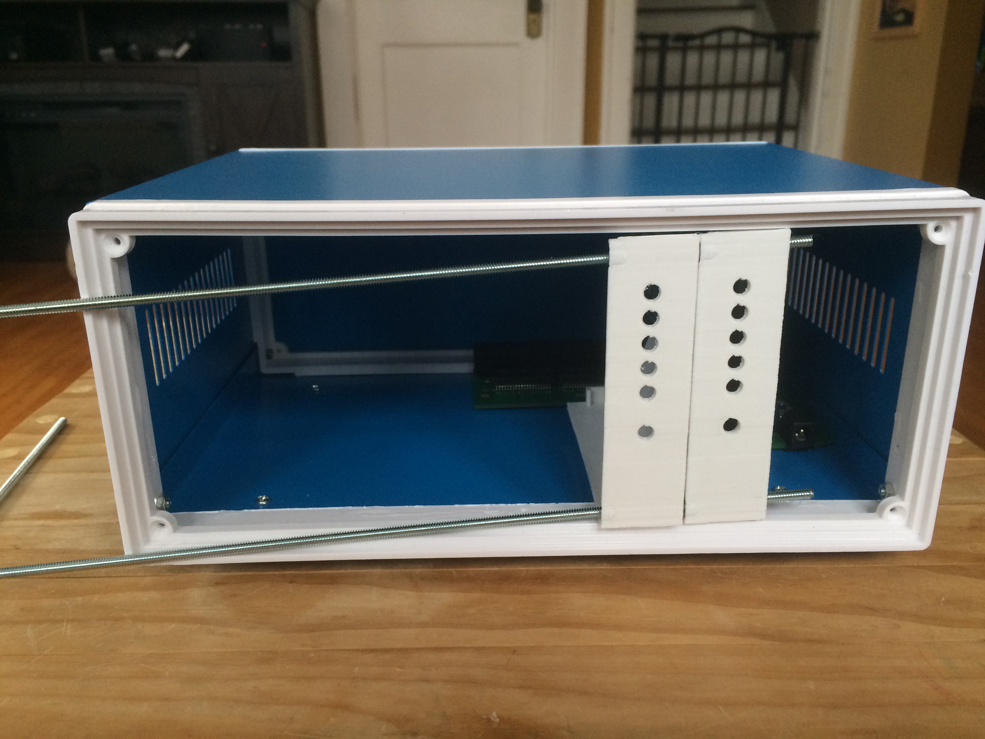 We also lose ~6mm on the left due to the screw mounting holes for the front panel. If I can get the module width under 24mm I might be able to make 8 modules fit, but it will probably require the left-end module to be tweaked to fit around the panel mounting screws, and will require a change to how I had planned to mount the power rails to the panel. While I was at it I fit the modules together on the power rails and noted a number of improvements to be made.
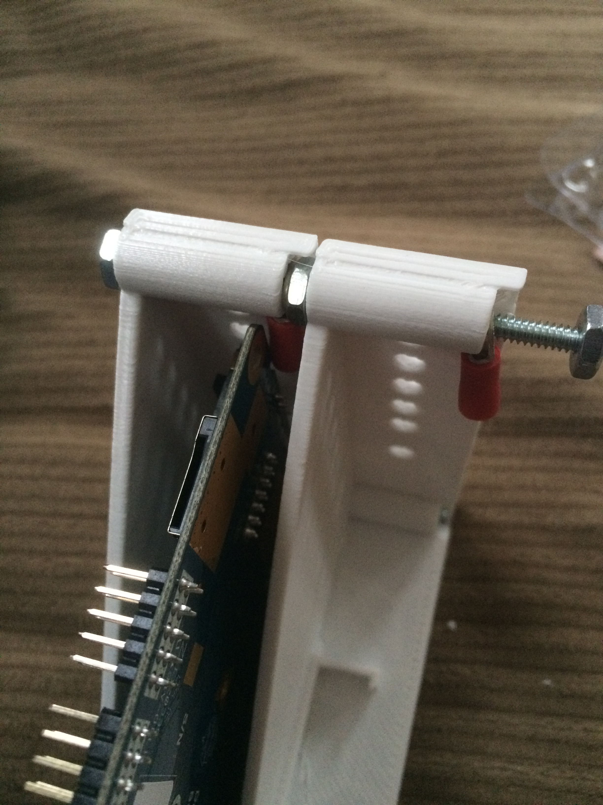
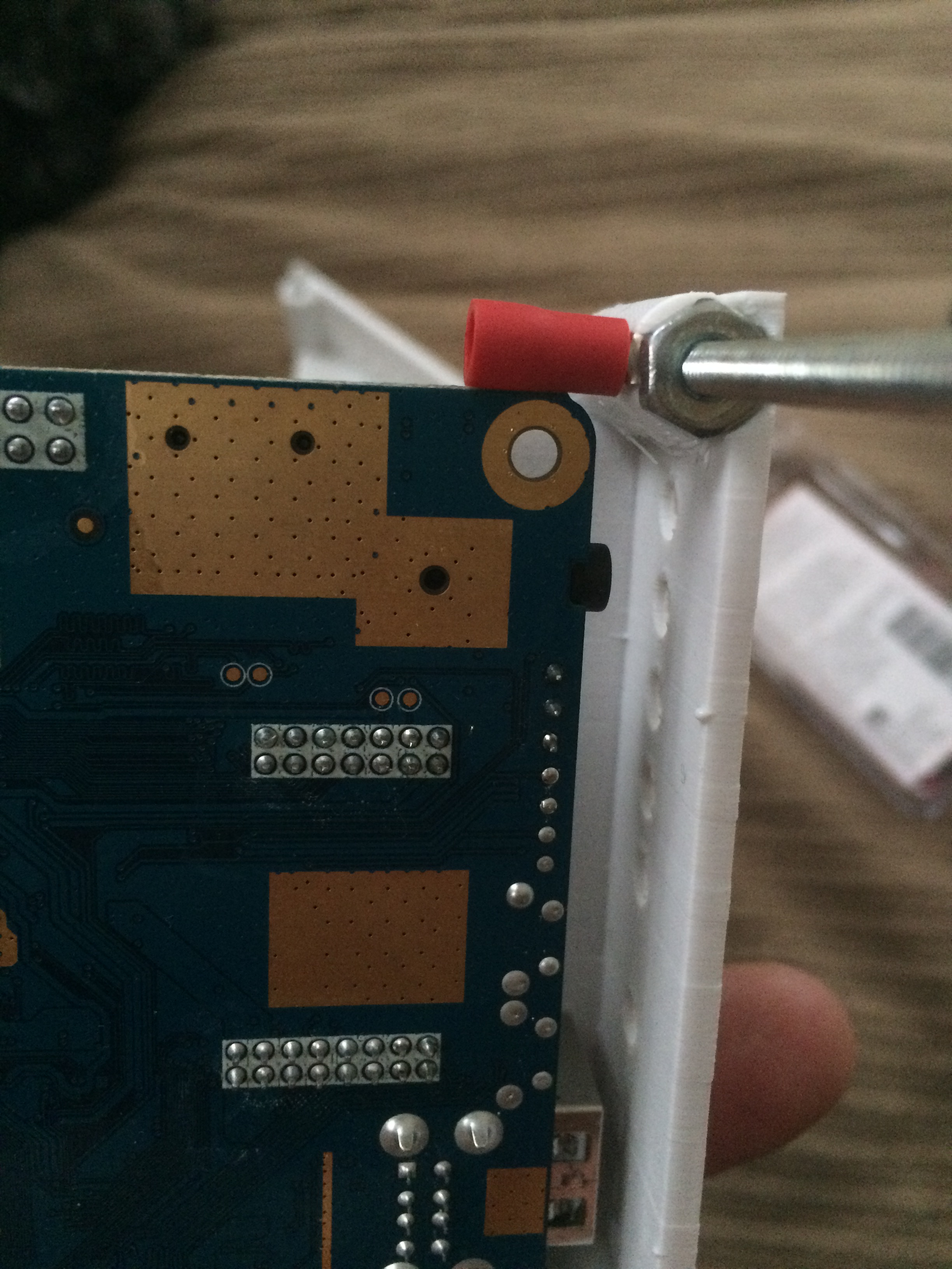
- Add 1mm more gap for nut and power lugs
- Reduce power rail hole by 1-2mm
- Power lug interferes with board on the top, maybe push board back 1-3mm
- Power lug interferes with the board at the bottom too, maybe sink board another 1-2mm into brace? Or, orient power lugs vertically, then they clear the board and provide a clearer path for the power wiring
- Power rail “bosses”(?) could have thinner walls to make more room for the wire barrel part of the power lugs (they are OK when they print correctly but print errors make the fit too tight).
- LED holes seem too small, but could be due to printer error
- Switch hole is too small, could be print error or might just need .5mm more room
- Bus connector could be raised about 1-2mm from bottom plate
- USB connector clears the switch but barely. The electrical connectors on the switch are accessible on a regular Pine64 but may be occluded on a board with WiFi
- Overall thicknesses could probably be reduced, the part is plenty strong and the stack-up on the front panel might be too deep for switches and LED’s to poke-through at the current thickness in addition to the changes above, I need to tweak the mounting holes for the front panel LED’s and switches to match the layout of the lasercut panel. There’s probably a clever way to figure this all out in software, but since I’m using two different programs to model the modules (OpenSCAD) and front panel (Inkscape) I’m not aware of a simple way to do this. Even if I could it would probably take some cut-and-try work because parts don’t come off the printer exactly how they look on-screen, and I imagine there is some tolerance to consider in the lasercut parts as well. The good news is that I have everything I need to iterate on this design “quickly” in the lab, so with some luck I should be able to get this sorted in my free time and with any luck have something that fits together nicely by the end of the month.
Comments
Shane: Hi Jason! I hope you find the comments useful! I just put together a Delta printer- a Tevo Little Monster. I am still going through the process of bringing it up, but it seems to be pretty accurate. It has a crazy large build volume- 340mm circular by 500mm vertical. I have a high power rocketry hobby for which I have purchased the Tevo to make avionics bay components and general parts. Not sure I’m going to use it for aerodynamic parts, especially for Mach speed plus airframes. But I digress… 🤨 A material other than ABS that gains favor is many circles for its dimensional stability is PLA- poly lactic acid. It is supposedly stronger than ABS, but it is biodegradable- OK for chochkies, but I’m not convinced I want to bother with it if it can break down over time.
Jason J. Gullickson: Thanks for the feedback Shane! I spent a lot of time doing this sort of calibration on the Reprap printer I built, but I have to admit I haven’t done much with the printer I made these parts with (a Monoprice delta). I could probably improve the tolerance if I took some time and learned to calibrate it (the delta is so much different I don’t know much about tuning it yet).
Shane: The dimensional errors you are experiencing with the 3D printed parts may be due to not having the 3D printer calibrated. Try making a cube 12.5 2mm on a side (0.5”) in your CAD software and print it out. Get a good pair of calipers ($25 or so at a place like Harbor Freight) and measure the printed cube in the X, Y, & Z dimensions. My printers print this calibration cube accurately down to 3 decimal places. Once you know your printer is calibrated, make sure you allow for some tolerance for things like the diameter of the LED- make the hole about 1⁄3- to 1⁄2 mm larger than the LED’s diameter measured on the body, not the base of the LED. Same for the switches, screws, nuts, & bolts you are using. Also, be aware the ABS plastic has something like 3% dimensional change due to temperature from hot to cold, so make sure all your measurements are taken when the part has cooled to room temperature. This should help you reduce your interactions to bare minimum. As an example for encouragement, I can tell you that I now largely can use my first prototype as a “final production “ functional part. I wish you luck with your project!