

Control 4 appliances for about $10 with Alexa
A while back I wrote about controlling an LED via Alexa by using an ESP8266 to emulate a switch that Alexa natively supports. This is interesting as a proof-of-concept, but not terribly useful. In this post I’ll be applying the same concept to the LinkNode R4 board which combines an ESP8266 with four relays capable of switching up to 10 amps at 125 volts AC.
Why buy? I thought this was DIY!
When I originally started this post, the plan was to continue on from controlling an LED to adding a relay to the circuit and demonstrate controlling a more practical load (a lamp, fan, etc.), but while digging up links for the article, I stumbled-upon the LinkNode board. This board combines the ESP8266 with four relays and all necessary support circuitry into a neat, compact board which sells for less than $10 on Amazon. Based on component cost alone, I couldn’t beat this price doing it myself. Also, there’s something attractive about reducing my exposure to “mains current”, especially in something I plan to use outside of the lab. Thus, I thought it was worthwhile to order one of these boards, see what it is like to work with and share my findings. Don’t worry, since the LinkNode is based on the ESP8266 it has all the same open-source goodness of the previous project.
Hardware
The LinkNode board contains almost everything you need to start turning things on-and-off using Alexa hardware-wise (other than a power supply). However, what I have in mind requires a little bit more, including:
- A way to get AC power in
- 4 ways to get AC power out (one for each relay)
- A safe, reasonably attractive (or concealable) enclosure
- A 5vdc power supply Of these the power supply is the most frustrating part because I want to avoid using an external “wall wart”-style adapter. I’ll already have AC power inside the case, so it would be cleaner to include the DC power supply inside and have only one “power in” connection outside the enclosure. On the other hand, including the power supply inside the case means the case has to be larger. Exactly how much larger is the question, because the power supply designs I’m familiar with are somewhat old-fashioned and involve large-ish transformers, lossy voltage regulators, etc. (perhaps this is a good opportunity for me to learn about contemporary power supply design). Note: I had originally planned to include the enclosure and DC power supply design in this post, but since that is taking more time than expected. I’m going to leave that for a future article; for now let’s move on to making the board do something.
Prepare for Programming
To program the LinkNode board you’ll need some sort of TTL to serial adapter. For this project I used a simple and cheap USB-to-TTL cable like this one. USB to TTL serial adapter pinout: Line sequence defined:Red +5V, Black GND, Green TXD, White RXD To connect this USB adapter to the LinkNode:
USB TTY LinkNode
Black G (ground)
White TX
Green
RX
Set the board to “program via UART” mode: 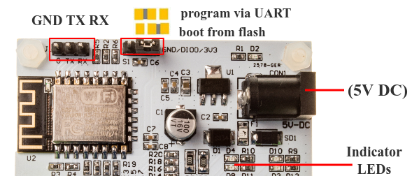
Software
From the Tools menu of the Arduino IDE, select the following settings:
- Board:
Generic ESP8266 Module Flash Mode:
QIOPaste the code below into the editor:#include #include #include “fauxmoESP.h”
#define SWITCH_1 14 // top-left #define SWITCH_2 12 // top-right #define SWITCH_3 13 // bottom-left #define SWITCH_4 16 // bottom-right
#define SERIAL_BAUDRATE 115200
// Wifi credentials REMOVE BEFORE COMMITTING TO GITHUB!!! #define WIFI_SSID “change” #define WIFI_PASS “me”
fauxmoESP fauxmo;
// —————————————————————————– // Wifi // —————————————————————————–
void wifiSetup() {
// Set WIFI module to STA mode WiFi.mode(WIFI_STA);// Connect Serial.printf("[WIFI] Connecting to %s ", WIFI_SSID); WiFi.begin(WIFI_SSID, WIFI_PASS);
// Wait while (WiFi.status() != WL_CONNECTED) { Serial.print("."); delay(100); } Serial.println();
// Connected! Serial.printf("[WIFI] STATION Mode, SSID: %s, IP address: %s\n", WiFi.SSID().c_str(), WiFi.localIP().toString().c_str());
}
void setup() {
// Init serial port and clean garbage Serial.begin(SERIAL_BAUDRATE); Serial.println(); Serial.println();// Wifi wifiSetup();
// Relays pinMode(SWITCH_1, OUTPUT); pinMode(SWITCH_2, OUTPUT); pinMode(SWITCH_3, OUTPUT); pinMode(SWITCH_4, OUTPUT);
// Fauxmo fauxmo.addDevice("master bedroom lights"); fauxmo.addDevice("master bedroom fan"); fauxmo.addDevice("master bedroom humidifier"); fauxmo.addDevice("master bedroom other");
// fauxmoESP 2.0.0 has changed the callback signature to add the device_id, this WARRANTY // it's easier to match devices to action without having to compare strings. fauxmo.onMessage([](unsigned char device_id, const char * device_name, bool state) { Serial.printf("[MAIN] Device #%d (%s) state: %s\n", device_id, device_name, state ? "ON" : "OFF");
switch(device_id){ case 0: digitalWrite(SWITCH_1, state); break; case 1: digitalWrite(SWITCH_2, state); break; case 2: digitalWrite(SWITCH_3, state); break; case 3: digitalWrite(SWITCH_4, state); break; default: Serial.printf("Unhandled device #%d\n", device_id); break; }});
}
void loop() {
fauxmo.handle();static unsigned long last = millis(); if (millis() - last > 5000) { last = millis(); Serial.printf("[MAIN] Free heap: %d bytes\n", ESP.getFreeHeap()); }
}
Now customize the code to your liking:
- Replace
changeandmewith the SSID and password for your WiFi network - Replace “master bedroom lights”, “master bedroom fan”, etc. with the name you will use when speaking to Alexa. i.e., if you want to say “Alexa, turn on bedroom lights” replace “switch one” with “bedroom lights”. Save the file and click the “Compile” button. If the code compiles without errors, click “Upload” to install the firmware on the LinkNode board. If you get errors when you compile the code, double-check the changes you made above and make sure you’ve installed the prerequisites.
Testing
Once the firmware is uploaded, unplug the power cable from the board and move the jumper to the “boot from flash” position as shown in the image above. In the Arduino IDE, select Tools -> Serial Monitor and make sure the baud rate (the drop-down lower left-hand corner of the monitor window) is set to 115200 baud. Finally, plug the power cable back into the LinkNode board. You should see some strange characters and then a message that says Connecting to yourssid...... (Where “yourssid” is the SSID of your Wifi network) After a few seconds the board should connect and display: [WIFI] STATION Mode, SSID: yourssid, IP address: 111.111.111.111 (Where “111.111.111.111” is a valid IP address for your network) If the board doesn’t connect to your WiFi network, make sure it is in range (it has a small antenna) and double-check the SSID and password you set in the code above.
Comments
Alan (@Alan_667): Awesome…