Charity Arcade - Electronics
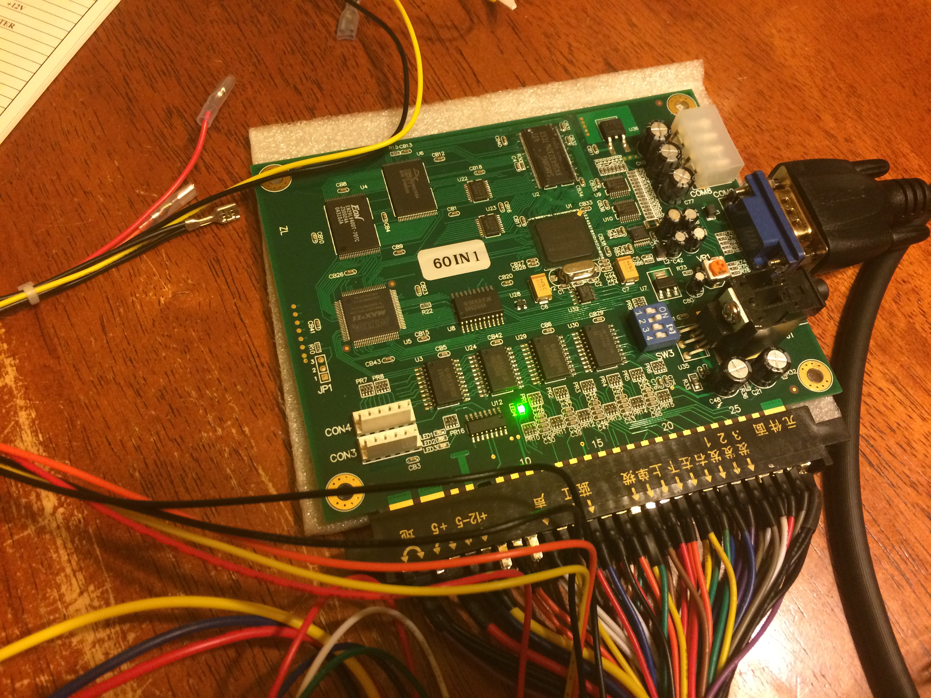
While the electronics are off-the-shelf, the documentation available is not exactly straightforward. Here’s what I’ve been able to decipher so far.  The 60-in-1 board uses the standard JAMMA connector, however it also includes a few modern connectors as well:
- A VGA video connector
- A Molex power connector
- An 1⁄8” stereo audio jack
- 2 Mystery connectors
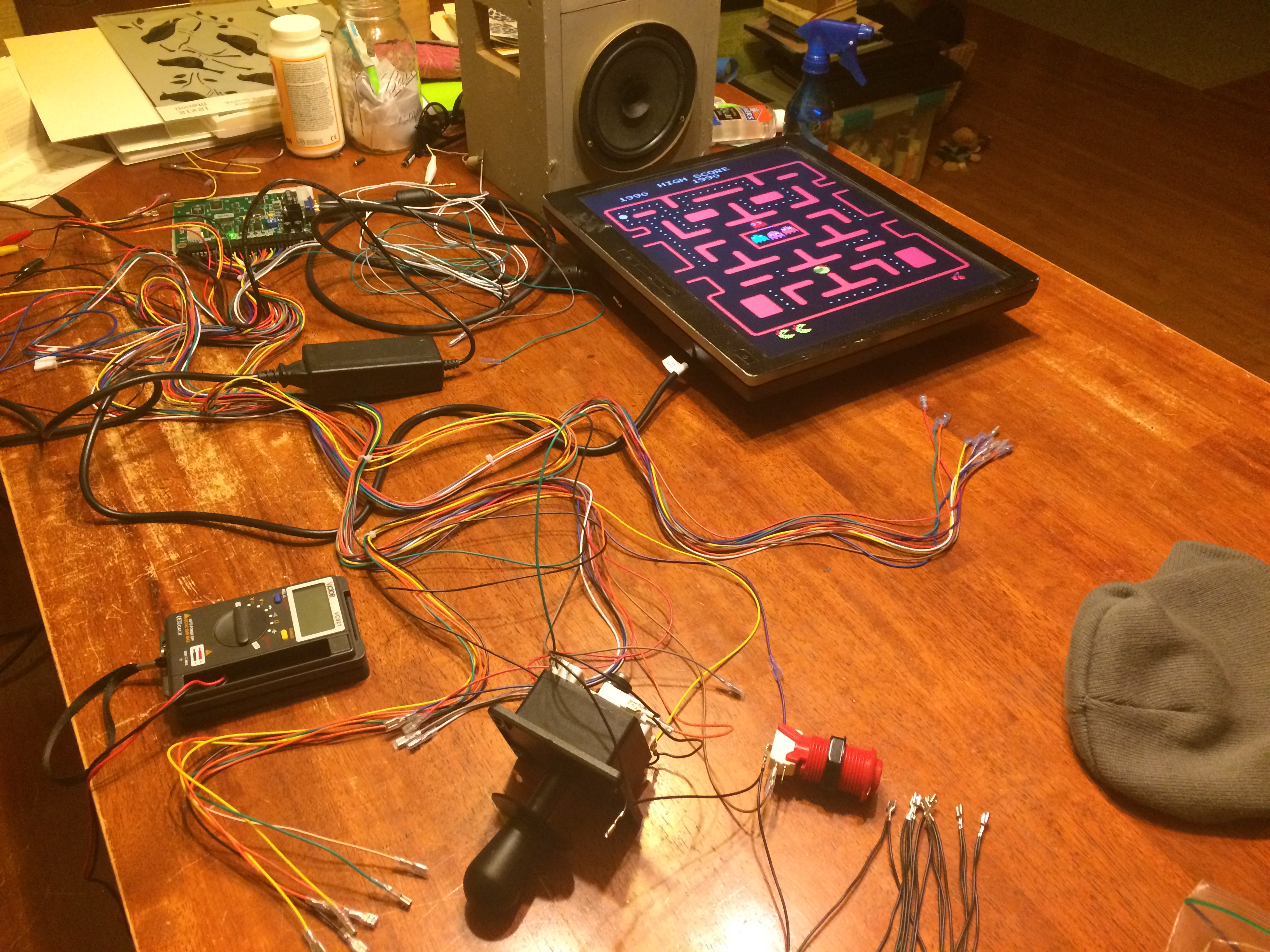
I struggled a bit to get a handle on what the power supply requirements are for the JAMMA board. After a number of conversations (and a lot of web searches) I found out that the Molex connector is exactly what it looks like; a standard PC-style power supply input. Of course I had already bought the wrong supply before finding this out. For some reason, I thought the JAMMA board only needed a 5VDC supply. This was a drag because I later found out that the coin slot I bought needs a 12VDC supply. Turns out the JAMMA board needs both 5VDC and 12VDC. The up side is that when I have the right supply for the JAMMA board I’ll have everything I need for the coin slot… I talked to my friend Jeff about this (he’s built one of these cabinets before) and he said that he just used an external hard disk power supply. I did some digging and found something like this in the parts bin and sure enough I had one already. I wired-up up the power supply via the JAMMA wiring harness because I knew I would need a 12VDC supply for the coin slot. Later (after talking to Jeff again) I found out that there are 12VDC supplies coming off the JAMMA connector to power things like the coin slot, so it makes more sense to connect the power supply to the Molex connector and then feed the rest of the system from the wiring harness. After noticing that the wires in the harness are bundled into groups that lead to the sections of the cabinet (the player controls, the coin box, etc.), it wasn’t too hard to trace the wires from the board to to figure out where to hook-up the joystick, start buttons, speaker, etc. With the basics wired-up I applied power to the board and it didn’t start on fire!
 I spent some time figuring out how to access the settings and configure the board as well as navigate around the game selection interface. We played a couple games of Ms. Pacman just to make sure everything was working properly.
  The goal of all this was to make sure the parts would work together and nothing was DOA with enough time before the deadline to order any replacements. Everything other than the coin slot tested out (I kind of forgot to try hooking it up). I labeled all the wires and tied things up with zip-ties so I won’t need the entire dining room table to hook it up next time, and through the process learned a number of ways to improve how things should be connected. There’s a few more things I want to test out with the electronics, and I have some more parts on-order that I’ll need to incorporate if they show up in time. In particular, I want to have a display which shows the total amount of donations collected. This will use an LED matrix installed in the “marquee” part of the cabinet, and use an Arduino (or perhaps an ATTiny ) to drive the display. I also want to add some illumination to the coin collection bin, perhaps controlled by the same brain as the LED matrix. We’ll see. Next time I’ll be diving into building the cabinet with my father. This is the part I’m most anxious about because I have a lot less experience with woodworking than I do with electronics. Fortunately my father has a lot more experience with this than I do, so I’m looking forward to diving into that with him.
References
- https://www.highscoresaves.com/60-in-1-icade-classic-arcade-multigame-jamma-pcb-board.html
- http://www.instructables.com/id/install-a-JAMMA-harness-in-an-arcade-cabinet/step7/Connect-speakers-and-coin-bundles/
- https://forums.arcade-museum.com/archive/index.php/t-120535.html
- http://arcadecontrols.com/BBBB/jh.html
- http://www.therealbobroberts.net/meter.html
