

Charity Arcade - Control Panel
In our last installment, dad sent me home with a board that was destined to become a home for the screen, controls and numerous hidden bits of the arcade machine. I call this the “control panel”. Last weekend we had a chance to dig into putting the “control” into the panel… We’d noodled on a number of layouts for the panel throughout the course of the project. After looking at a lot of existing designs and doing a few “usability tests”, we settled on a fairly basic layout for the controls loosely based on the mid-80’s Nintendo cabinets. This follows angular geometry of the rest of the design (no ergonomic curves here!), and gives us more horizontal room compared to designs that place the player select buttons in the same plane as the rest of the controls. 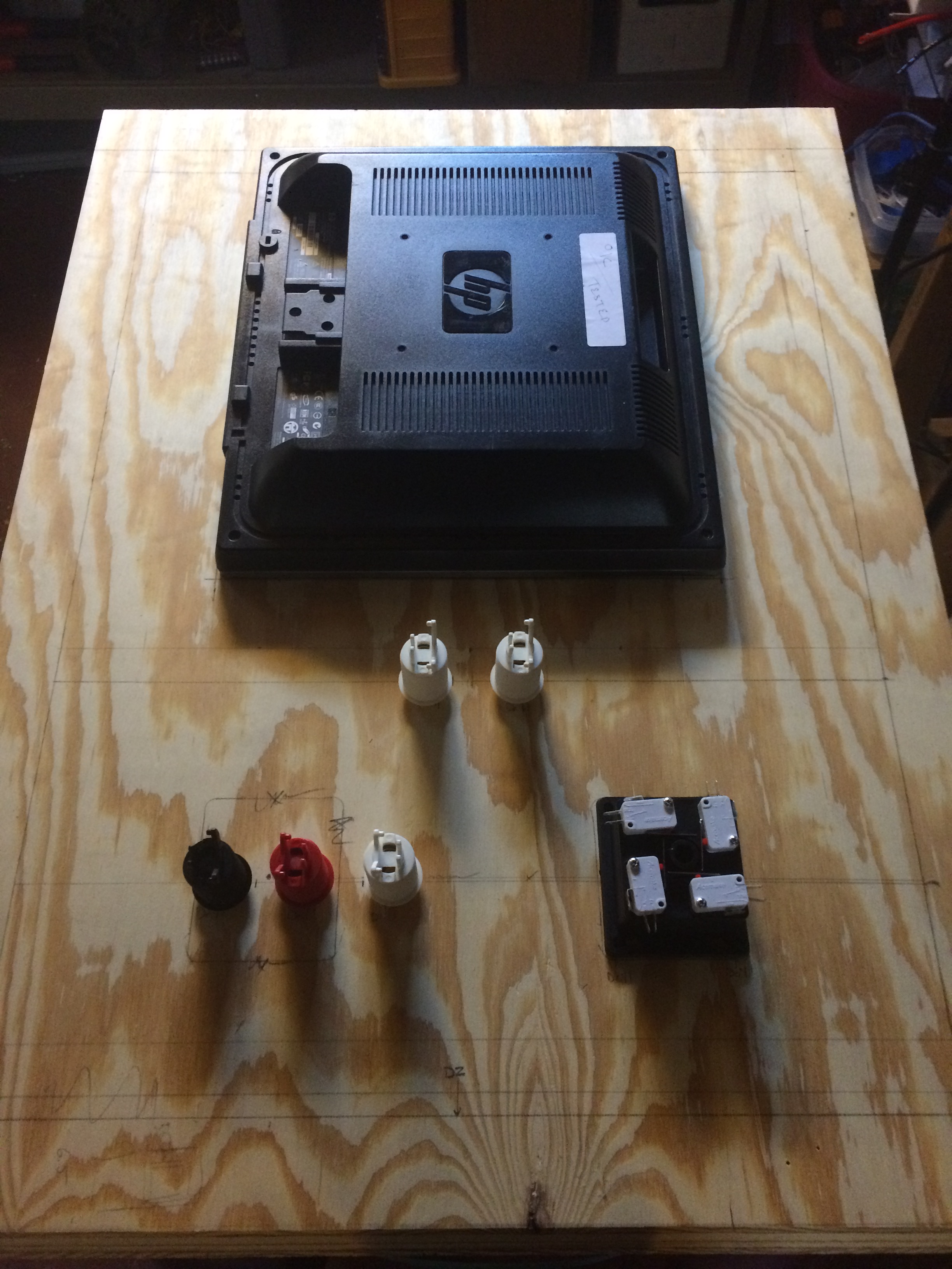 Once a layout was decided on, measurements were made and marks were placed. Next comes the cutting, which is of course where things get ugly (because they are less reversible). I knew that the most challenging part would be cutting the hole for the screen. This would involve a jigsaw, and cutting straight lines with a jigsaw is, in my experience, challenging. Unfortunately, that wasn’t the worst of it. The worst was that I had marked the board on the “inside” of the panel (thinking this would leave the outside cleaner), but on the first cut the saw readily made a mess out of the front of the panel. After this happened, I realized that I already knew that the nicer looking side of the cut is the side the saw is on, but for whatever reason I spaced this and the panel paid the price. So I knew I needed to make the cuts from the outside face of the panel, but I didn’t want to re-measure everything to transfer all the marks to the other side. I had already made a mistake marking the board earlier and I didn’t want to risk repeating something like that. So, after a little noodling it occurred to me that since everything was either a hole of a straight line, I could just drill small holes through the panel at the various points and then connect the dots!
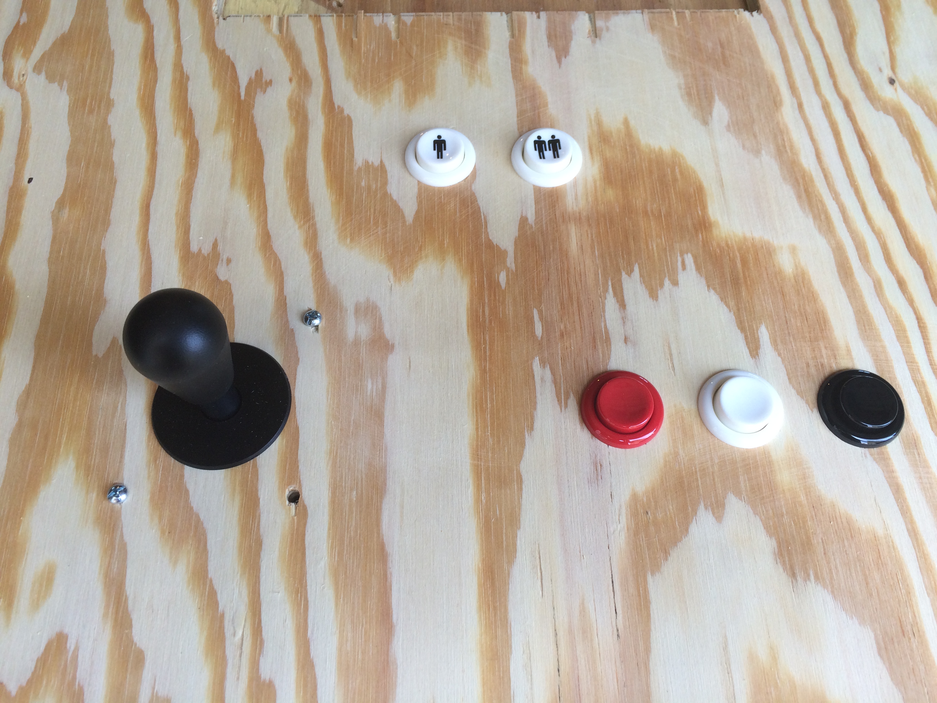
 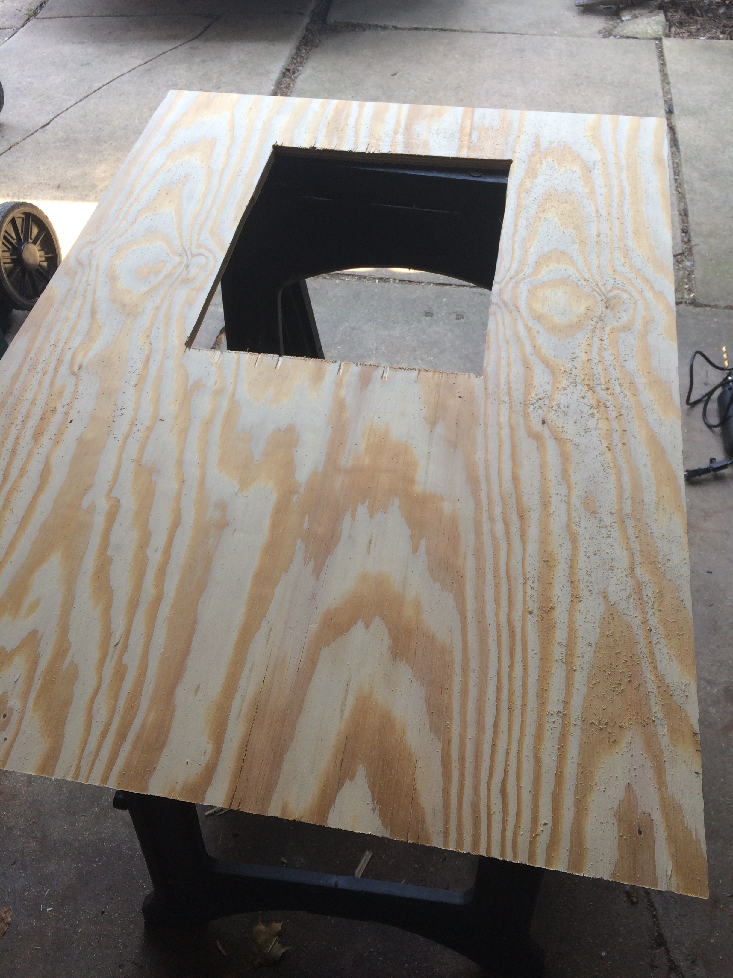 This worked well and after a few minutes I had the hole for the screen cut without making too much more of a mess out of the panel. Now it was time for the easy part, the round holes for the controls. Only this wasn’t so easy. I started with the buttons which are just slightly more than 1” around. For this I tried using a spade-style drill bit and basically got nowhere. I don’t know if the bit is dull or if it’s just a poor way to cut a hole in plywood but essentially all I got was a nice round indentation in the wood an a little bit of rustic-smelling woodsmoke. Instead of risking further damage to the panel, I headed to Fleet Farm to pick up a proper hole saw. I came back with a small Milwaukee hole saw kit which included a 1 1⁄8” saw which made holes that were almost a perfect fit for the buttons. The kit also included a 1 1⁄2” saw that was perfect for making a hole for the joystick.
 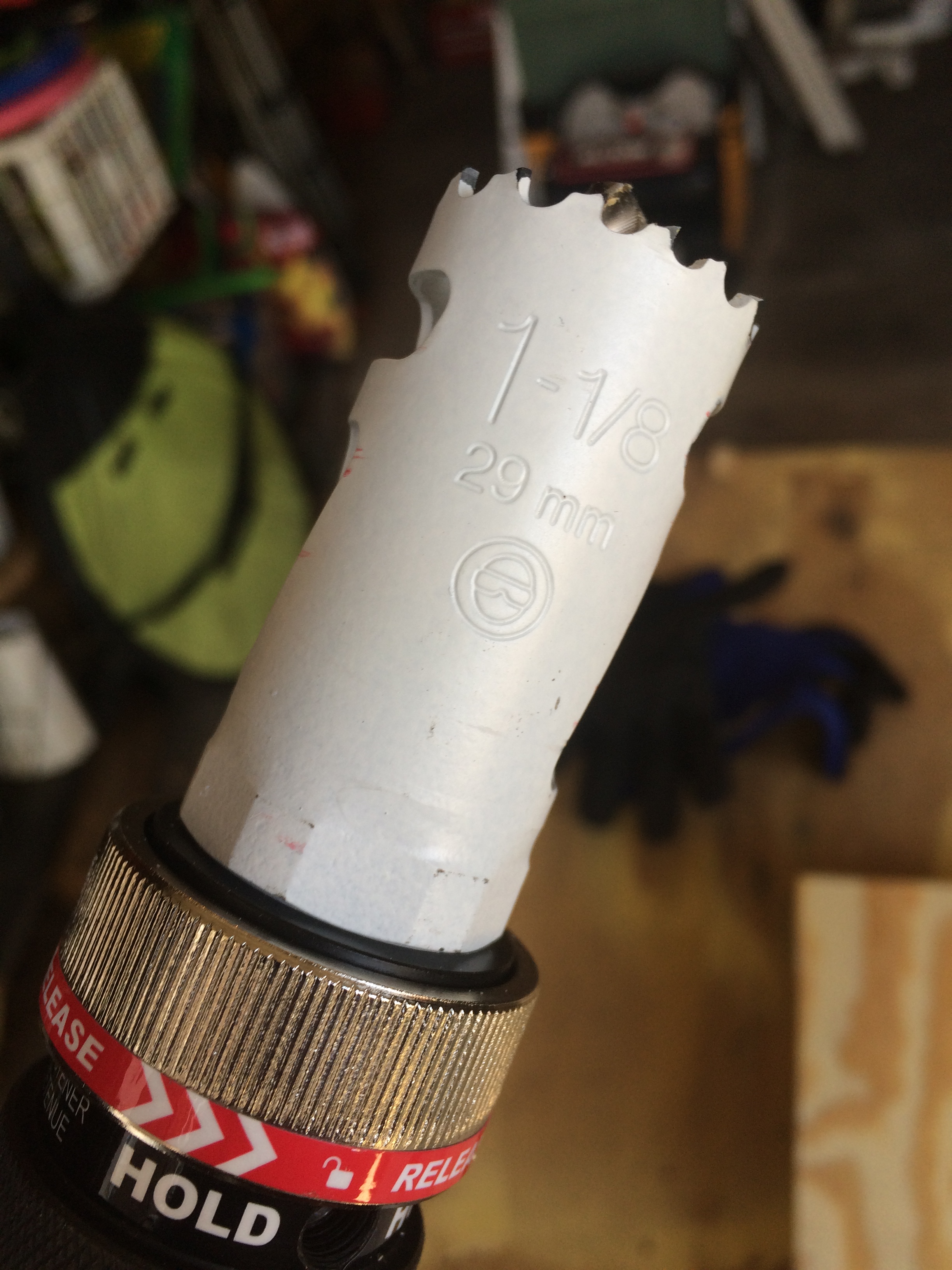 The hole saws made short work of getting the controls mounted, and after a little clean-up and sanding, everything fit right into place.
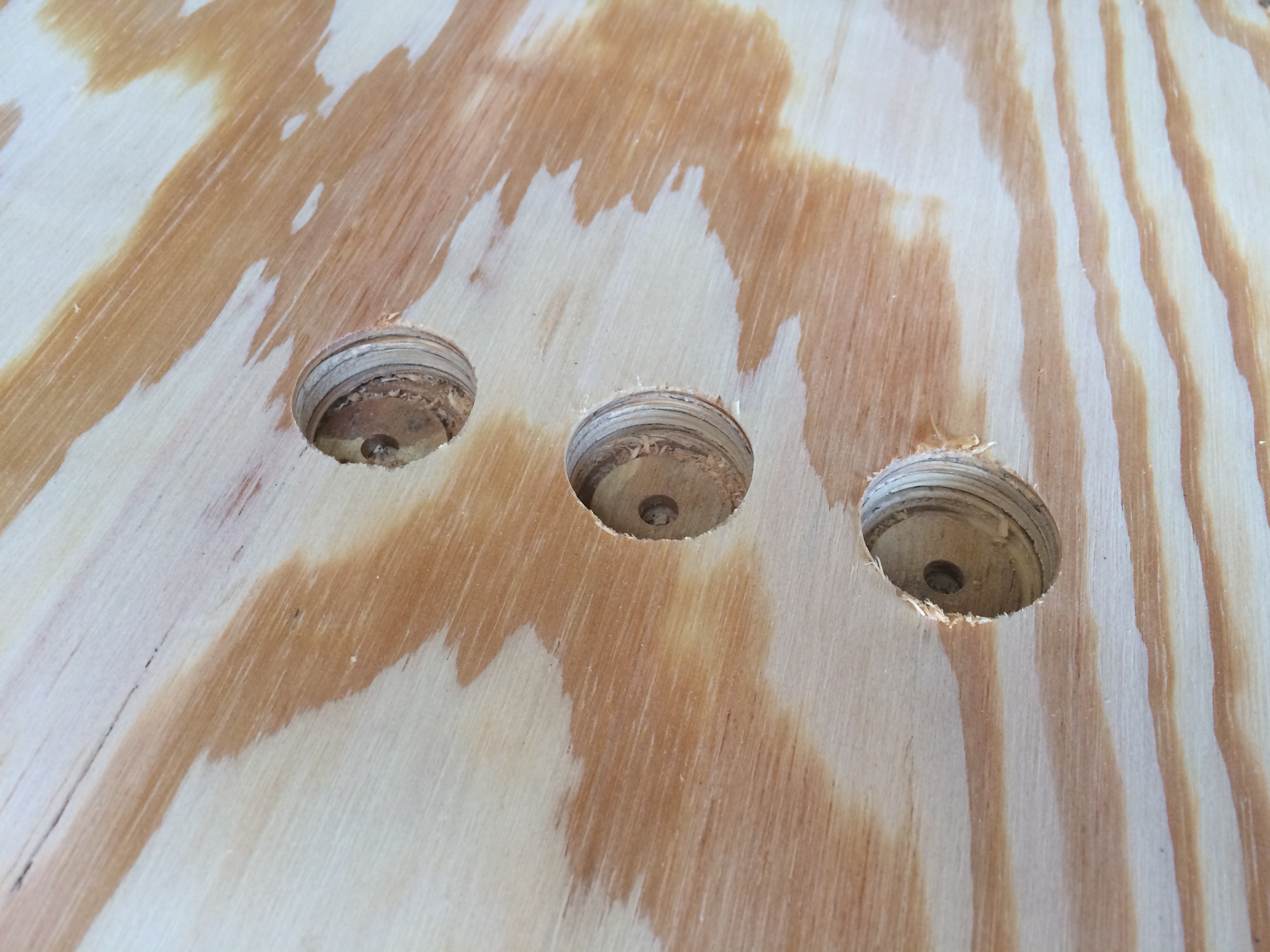
 After a test fitting, the controls were removed and Jamie spent some time giving the front of the panel a few coats of black paint. Once the paint was dry, the controls went back in and I moved on to the next challenge: attaching the screen. Beyond cutting a hole for it, I hadn’t given much thought to exactly how I was going to attach the screen to the panel. I had a number of ideas, but now that I could lay the screen on the panel, none of them seemed that great. The biggest concern was that the panel is only 1⁄2” thick, so it seemed like it would be hard to fasten anything to the back of the panel without having to pierce the face as well. Since it wouldn’t be a GL project if I didn’t find some way to drag 3D printing into it, I decided to experiment with modeling some parts to clamp-down the screen. I still didn’t feel confident that they would be strong enough without going all the way through the panel, but it was worth a try.
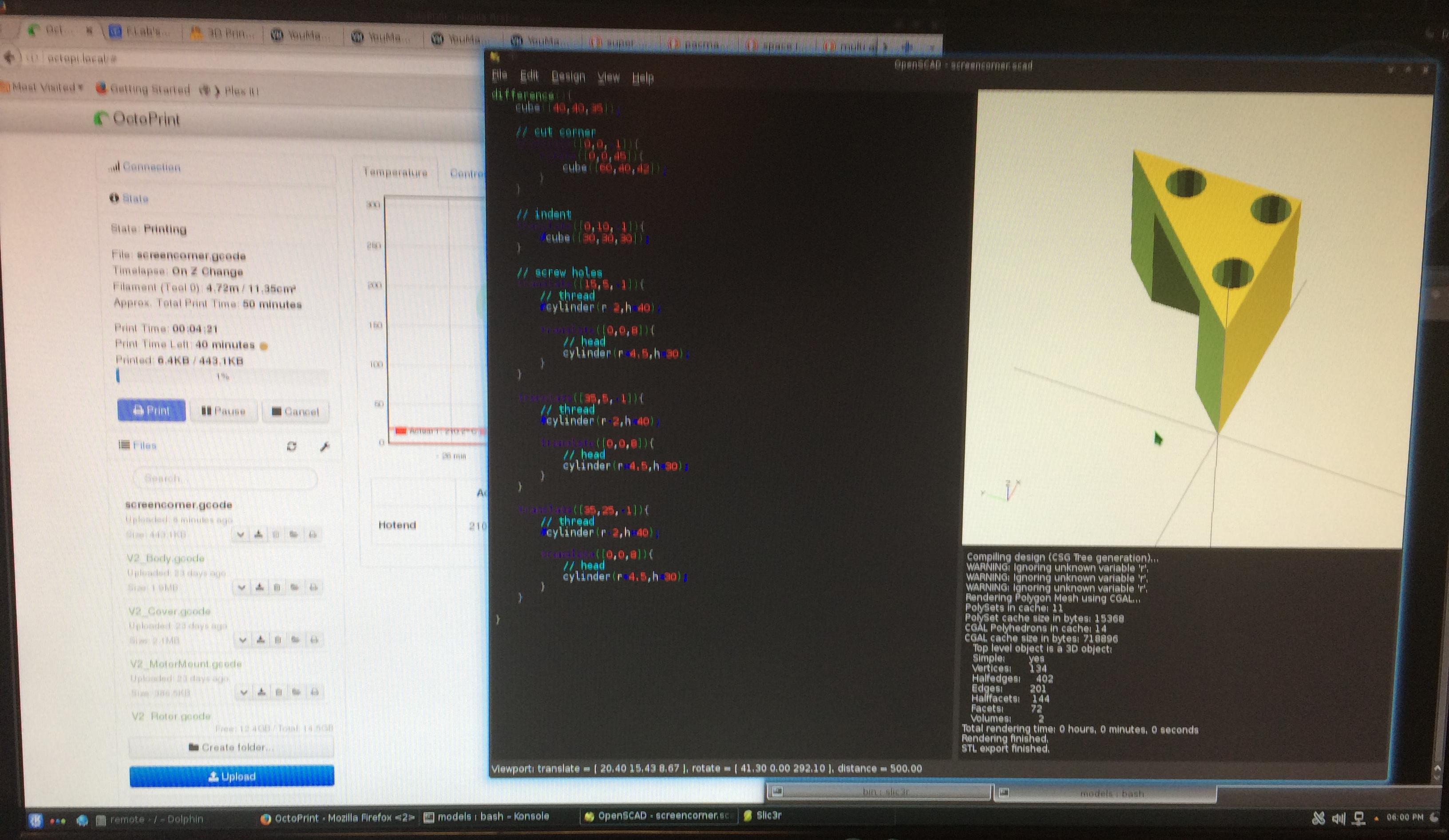
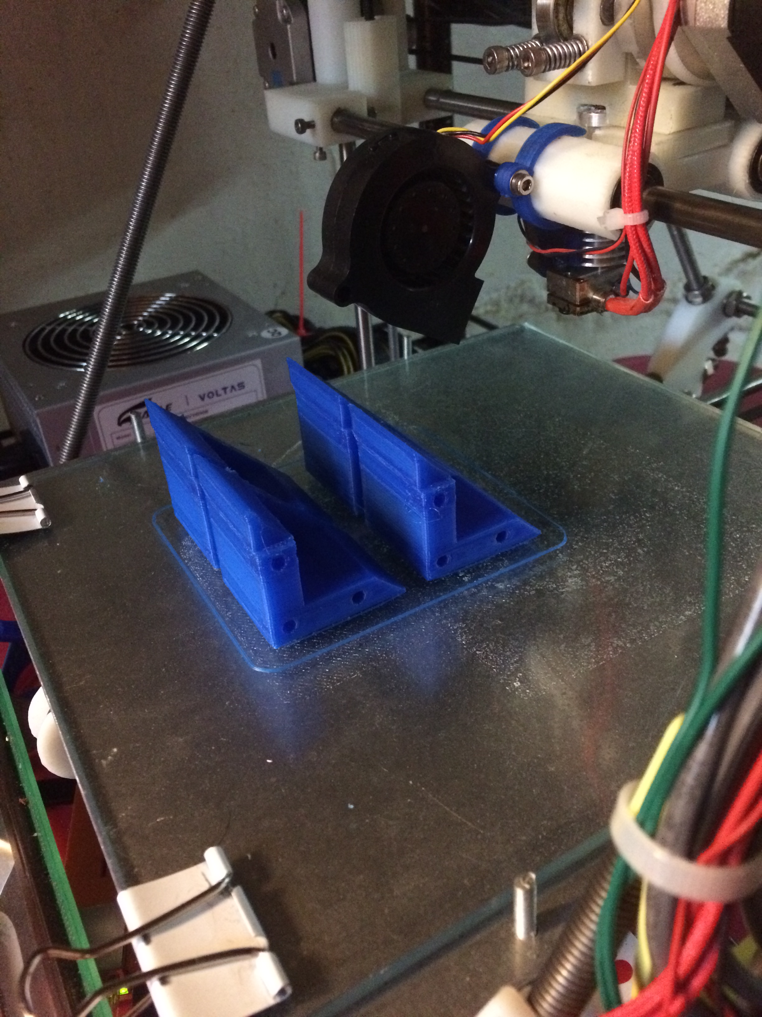 When I mounted the test part to a piece of scrap panel with three screws I was amazed to find out that not only was it strong enough to hold the screen, but I couldn’t pull it apart if I tried. Those three little screws were able to resist all the pulling and yanking I could manage, so I felt comfortable that four of those clamps could hold the screen in place under reasonable conditions.
 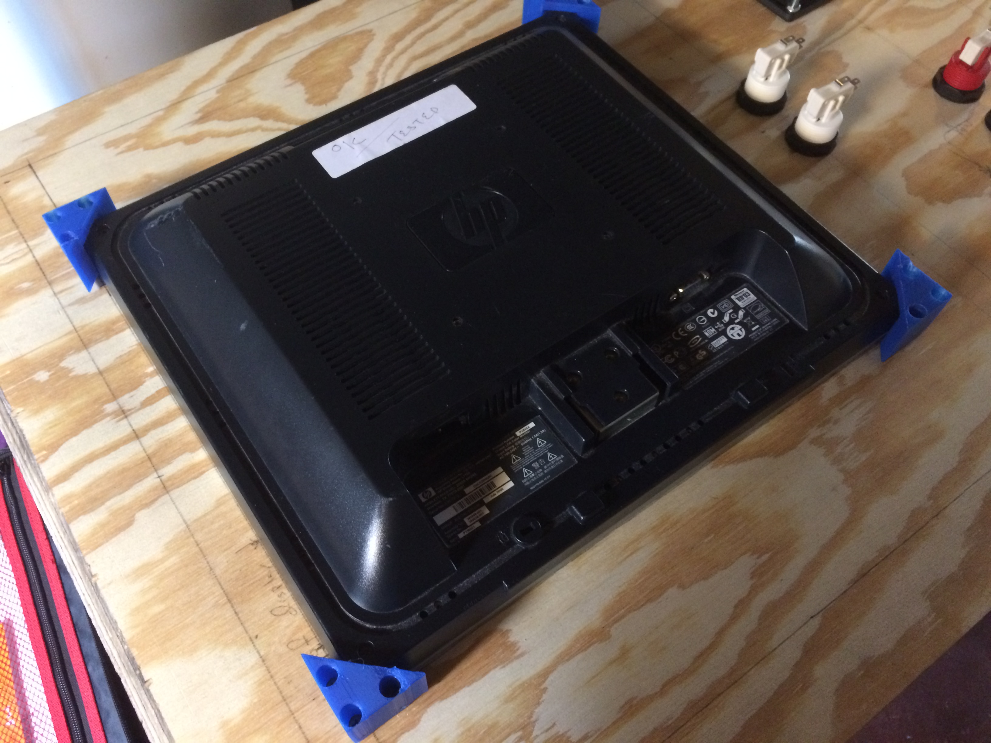 Next I needed to find a way to mount the JAMMA board and its power supply. I knew I wanted to mount the board to the back of the screen, and I imagined creating an adapter that would mate the mounting holes on the JAMMA board to the VESA mounting holes on the screen. However for now I just cheated and lined one of the board’s mounting holes up with one of the VESA mount holes, and then used a self-tapping screw in the opposite hole of the board to thread into a ventilation hole of the screen. This is cheesy, but good enough for testing until I fabricate a proper adapter.
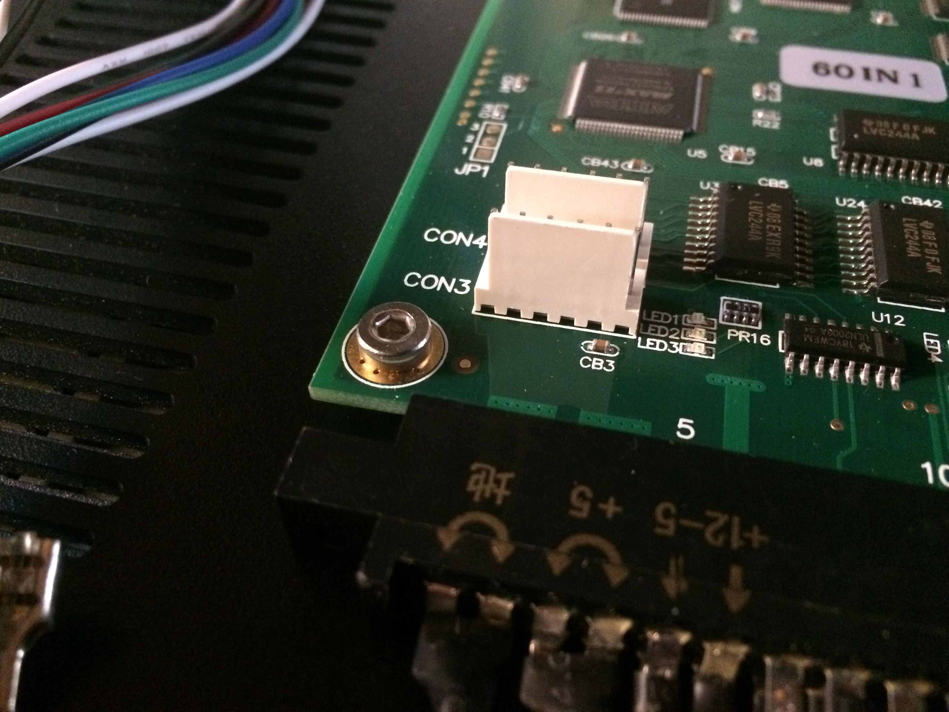
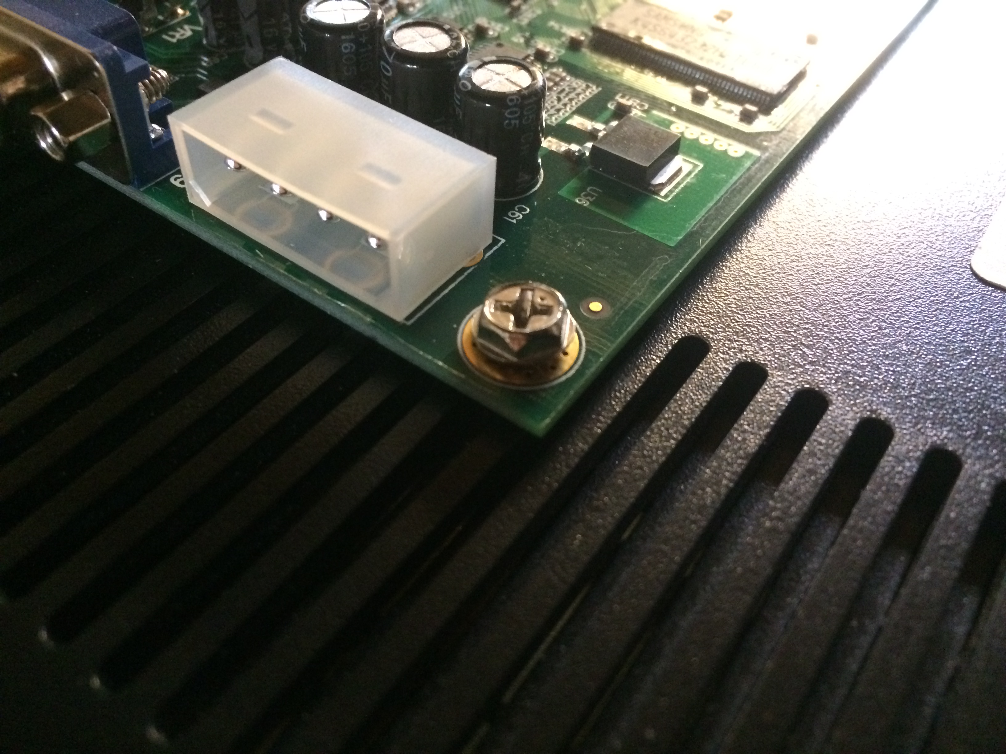 Pinning the power supply to the panel was simply a matter of securing the input and output cords using cable clamps. I might do something more sophisticated in the long run but this seems adequate. Now that things are tied-down I could start wiring things up to test out the system. Since I had done this once before I didn’t expect any surprises, but I did notice one small problem when I booted the system up the first time.
 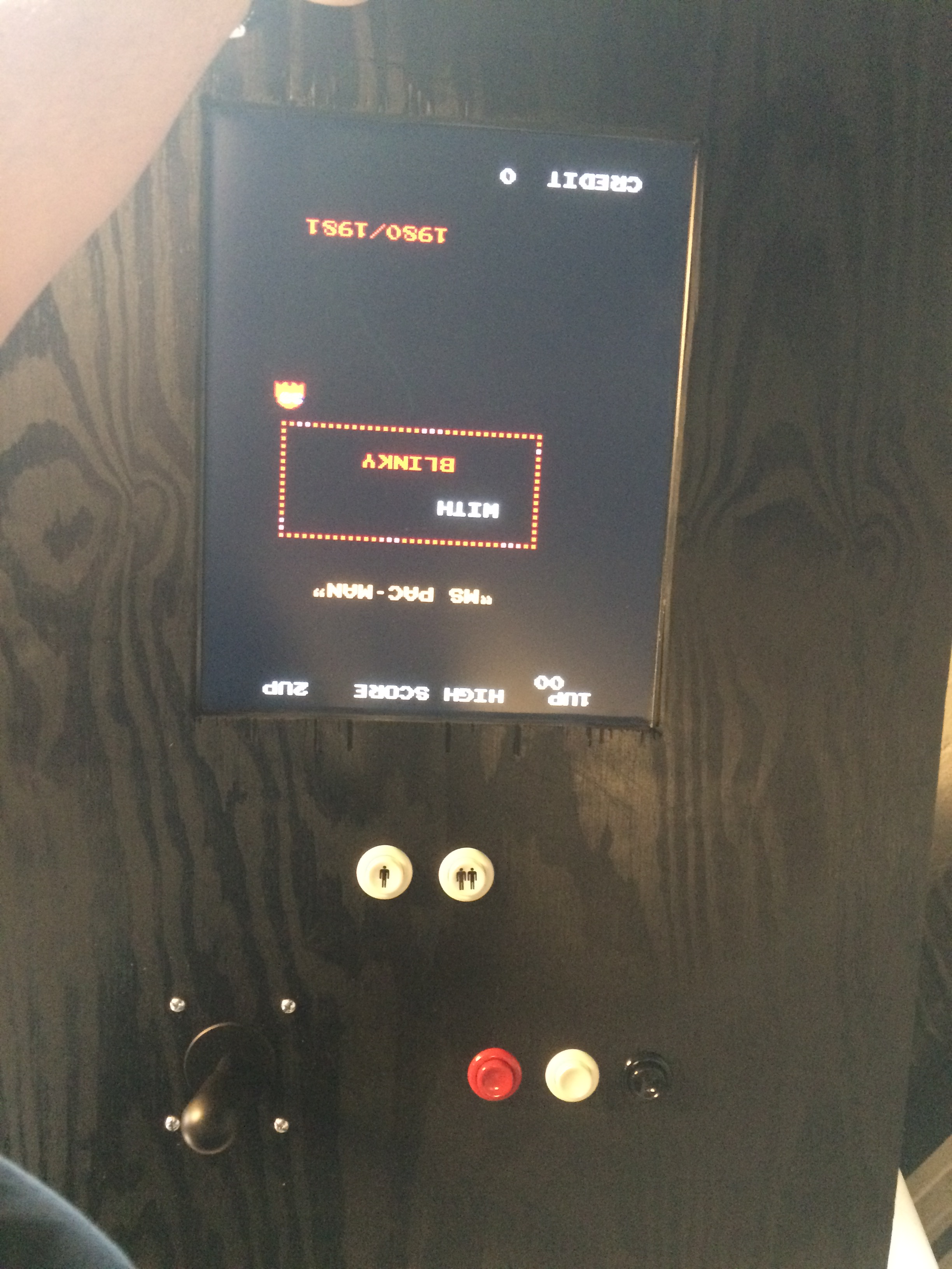 Fortunately this was easily remedied by flipping a configuration DIP switch on the JAMMA board, as flipping the screen physically would have caused some alignment problems. Once this was resolved, I tied a temporary speaker to the wiring harness and the system was ready for testing.