

Beginner’s Luck (KiCad Part 2)
Last time I left-off with a 2-D printed version of a printed circuit board I designed in KiCad which was enough to confirm that the board I was designing would fit into the board I’m designing it for. This felt like a lot of progress! 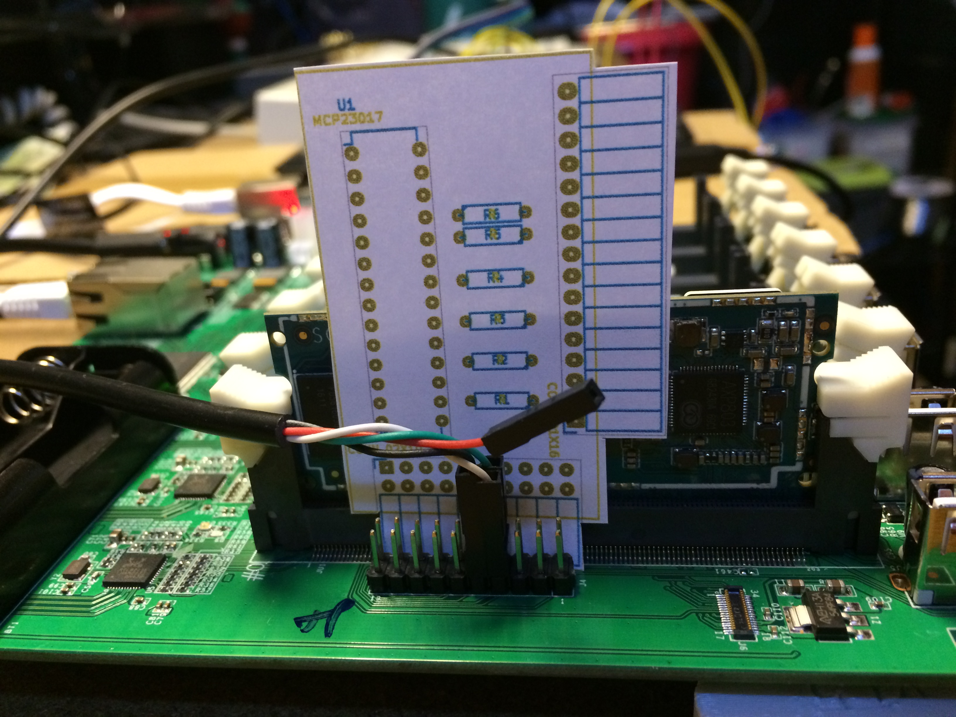 However there was still a lot to do, primarily consisting of making the actual electrical connections between the components on the board. For some dumb reason I thought this would be easy, but I ran into problems getting the traces to connect, or prevent them from overlapping, etc. Part of the problem is that I have no real experience in the more abstract (i.e., not related to learning the software) aspects of PCB design. Luckily Bob was willing to help me out and gave me a list of steps to use as a starting point when laying out a board:
- Lay out the connectors where they have to go
- Logically place groups of components where they need to go (power section should be in one area, microcontroller + decoupling caps in another area, etc.)
- Refine component placement to have as few overlapping airwires as possible to ease routing
- Route length sensitive traces first
- Route other traces
- Route power traces, but do a ground pour to make it easier
- Tidy up
- Lay out silkscreen and be as descriptive as possible
In addition to this, Bob said traces could be 6 mil wide minimum, but to aim for 10 mil in general and 12 mil for power. This advice helped a lot and between this an finding a “mode” for laying traces that worked for me, I was able to connect all the parts and get the board to pass the Design Rules Check (DRC). Bob eyeballed my layout, gave me some tips on improving it and said it looked like it would work.
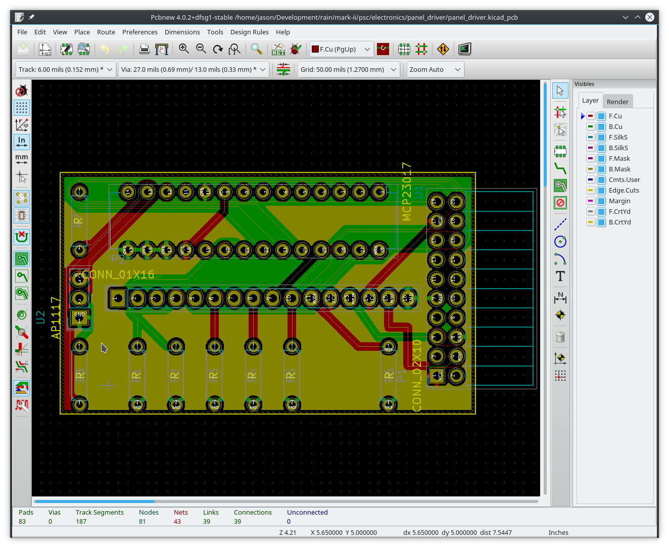 It was around this time that I noticed an error in the pin assignment where the panel driver board connects to the headers on the Clusterboard. Since the driver board will connect using a right-angle connector, but I designed it with a straight connector in mind, pin 1 would end up in the wrong place. This was easily fixed by rotating the connector on the board, but since this connector has traces leading to almost every other component, the layout became a complete mess. Instead of fighting with this, I took the opportunity to redo the board from scratch and apply everything I’ve learned so far. The second time around went much faster and I think it looks nicer as well.
 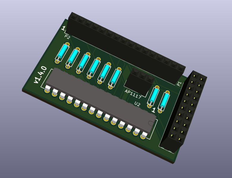 After reviewing the design (for what felt like the millionth time), I was reasonably sure I didn’t make another mistake like the connector and decided it was ready to upload to OSH Park for production.
 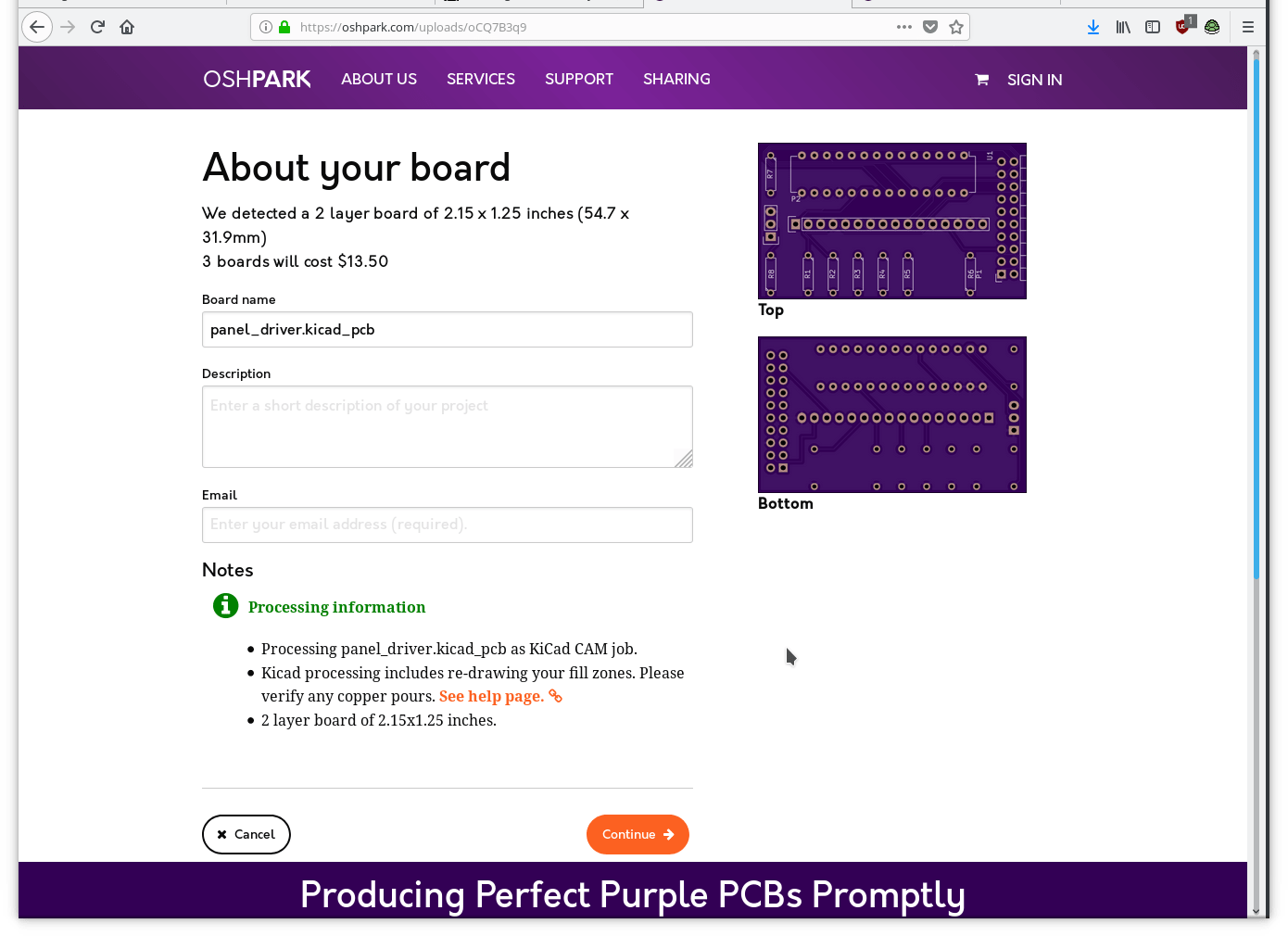 This process went very smooth. I don’t have any personal experience to compare it to (being the first board I’ve designed to be produced this way) but the website was easy to use, the visualizations and “checklist” guides were very helpful and I felt like I had a clear idea of what the final product would look like when they were done. Now it’s just a matter of waiting.
 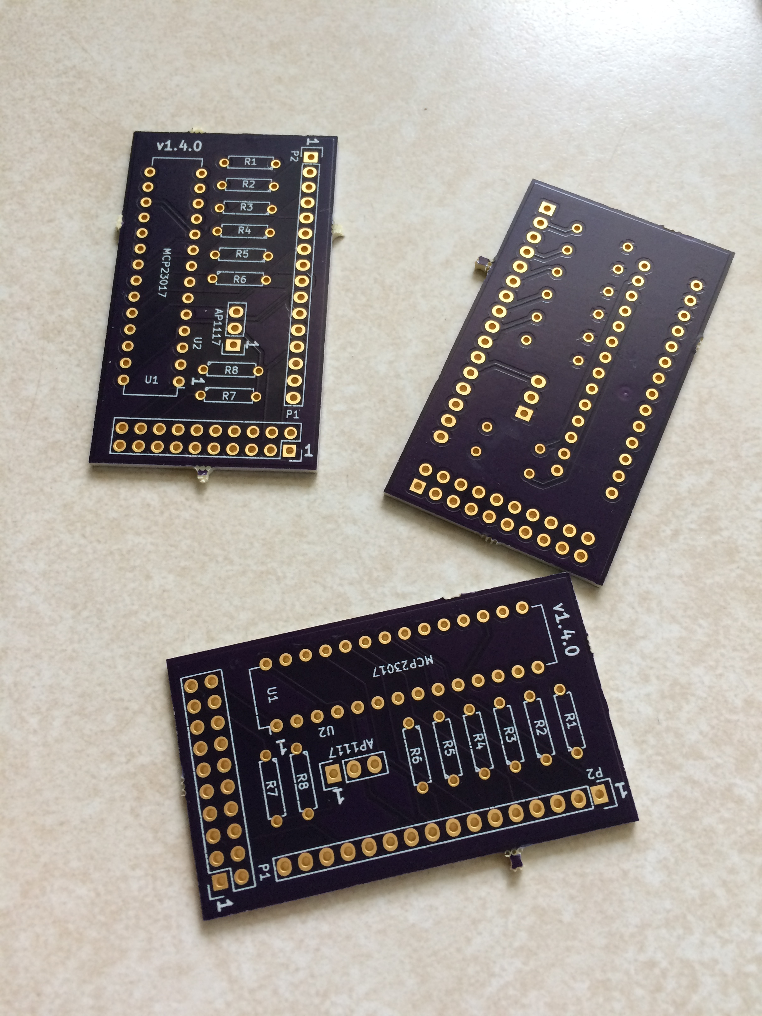 The boards showed up a few days early and I was lucky enough to have time to try one out (the minimum order was 3 boards). I had only enough parts on-hand to complete one, but this was intentional because I assumed that I would have made some mistakes and that I could order more parts after I fixed the design and re-ordered a second batch of boards. [gallery ids=“5157,5158,5159” type=“rectangular”] After assembly, I tried to quell my excitement and properly check-out the board in steps (inspired by Bob’s article) to reduce the chances of burning-up the new panel driver board or worse, the precious Clusterboard. [archiveorg 2018042115.38.41 width=640 height=480 frameborder=0 webkitallowfullscreen=true mozallowfullscreen=true] First, I tested the driver board alone to make sure power was flowing to the right places. Then, I attached it to the Clusterboard and checked the i2c bus to see if it was showing-up correctly. Finally. I wired-up the LED’s and toggle switch and ran the python script. [gallery ids=“5160,5161,5162,5163” type=“square”] Much to my surprise, the LED’s lit up and the switch correctly toggled between display modes! Something was not quite right in that the LED’s don’t illuminate in exactly the right order. It’s not clear yet if that’s a problem with the LED wiring or a design error on the board. The good news is that I might be able to correct this with a software change, so at least the boards themselves may be salvageable. Even if I have to make changes to the board to fix this, there’s a number of improvements I’d like to implement anyway so this won’t be the final version of the panel driver board regardless. It’s hard for me to express how exciting it was for me to complete this process. Learning to design circuits using an EDA is something I’ve put-off for a long time, but now that I’m getting the hang of it I can see so many ways in which learning to use these tools will expand and accelerate my ability to make things. There are many ideas I’ve had in the past that I didn’t pursue because I knew they would involve working with components that I couldn’t use with the old construction techniques, or that wouldn’t be practical to produce in any volume using those techniques.
 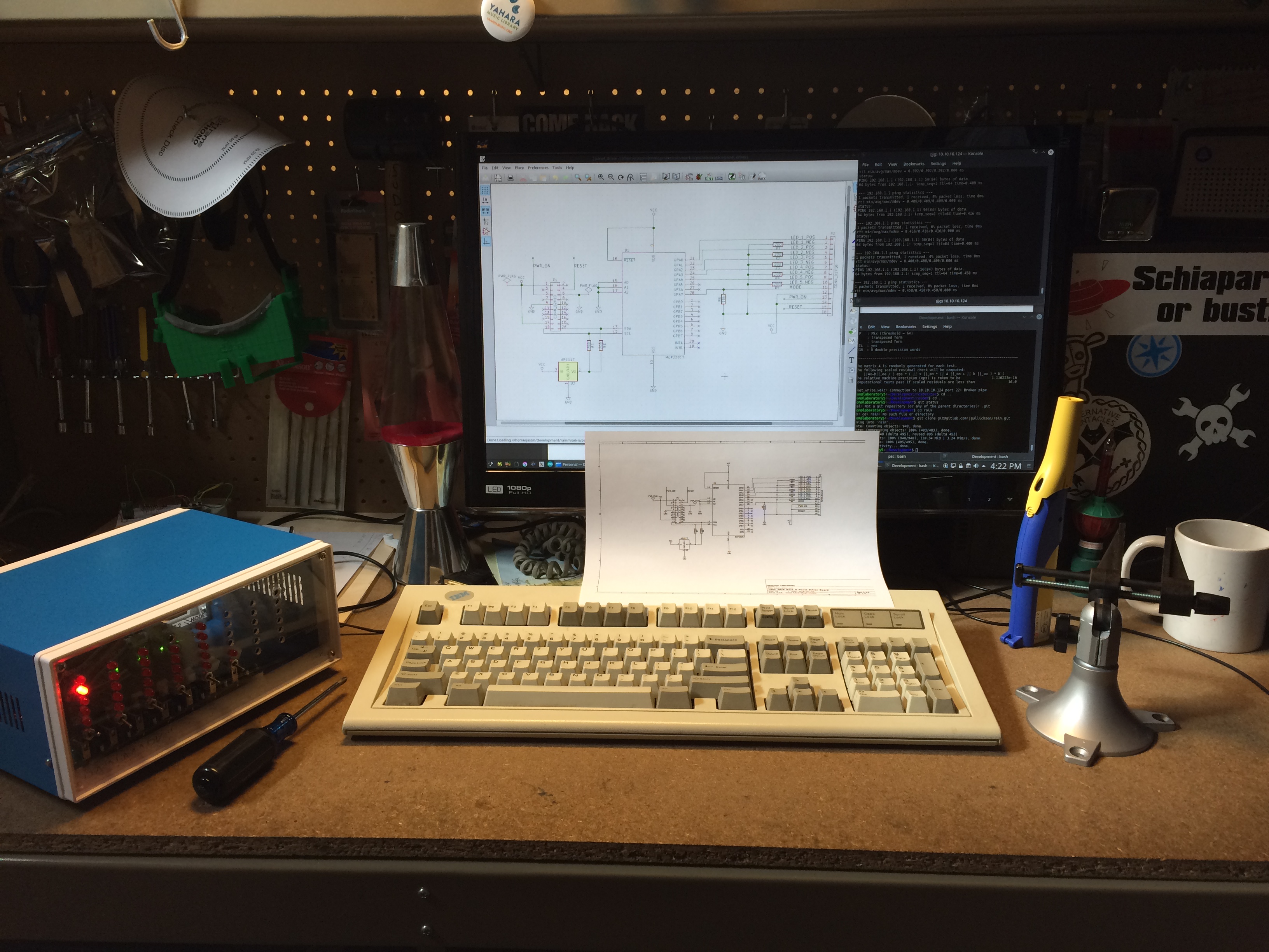 I have a feeling that learning these skills will be like building my 3d printer. Building the printer taught me a lot, but also opened my mind creatively by making it faster and easier to make both things I was already making but also things I never considered because I didn’t have the tools/skills/materials necessary.
Comments
pfeerick: I’m guessing the ports on the I/O expander going in opposite directions on each side was the cause of the problem? The chip manufactures don’t want to make our lives TOO easy! ;) So what are your thoughts as to how to actually make the cluster network boot… or are you not quite there yet? Is it going to be clusterboard wired to the pine64, and the pine64 does the DHCP & PXE boot serving, and then maybe wireless access to the pine64 for ‘hands-free’ access? As I tried to run … forget what it’s called now… dns-masq… service on one machine on my network to spoof the PXE boot for a rock64 (as I had it before I got the clusterboard) and whilst I could manually make it network boot, I couldn’t get it to automagically boot… It didn’t seem to be able to bet getting the magic packet that told it where the PXE server actually was, although dns-masq was logging the request and claiming it was responding… Just curious on your thoughts to this (or if it is a non-issue in how you’re designing the system).
Jason J. Gullickson: Long-term I’d like to have the nodes on the Clusterboard network boot using their on-board SPI flash, but I haven’t figured out exactly how to make that all work. For now I have the stand-alone PINE64 board acting as a “front-end” node providing DHCP and acting as a router between the Clusterboard’s network and my wireless network, similar to how the Mark I machine worked except it was all Ethernet (those servers had two wired Ethernet controllers in them). Do you know of a good guide to using the SOPINE’s on-board flash to boot over the network? I’ve seen a few things discussing the various components but I haven’t seen a concise guide that pertains specifically to this setup. After I wrap-up the hardware work I’ll be able to spend more time learning all the intricacies of this but it would be very convenient if I had a simple guide to follow for now :) Until then I’ll probably stick with this setup and add NFS to the mix so I don’t have to keep manually replicating the application binaries between hosts…
pfeerick: No, I’m afraid not. As the SPI is only 16MB (128Mbit), I’m thinking it’s not going to store much of an operating system, so I am thinking of doing exactly the same as you… PXE off the front-end/master node, and have NFS off the front end for both the OS and file storage. For the rock64, it was a process of running one of the /usr/local/sbin scripts to copy the uboot bootloader from the SD card (it may accept eMMC, not sure) to the SPI Flash, and then the rock64 was able to boot with no eMMC or SD card installed, opening up USB boot and PXE boot in its case. So I’ll try the same again for the sopine module, and hopefully get the pine64 to co-operate providing PXE boot info. Fingers crossed! :D
pfeerick: Hm, looks like the SPI UBOOT stuff is here (https://github.com/ayufan-pine64/bootloader-build/releases)... you write an image to the SD card or eMMC and boot an image that simply write uboot to the SPI. So the script to do it from the installed OS like on the rock64 isn’t there… this is quicker for the sopine… just boot each in turn, load uboot, and you’re done… but it would have been nice to have the option… wonder how transferable the script is. And just for reference, the SPI Flash chip is the Winbond W25Q128JV
Jason J. Gullickson: Awesome, thanks for all this info @pfeerick. I got pulled into some springtime projects and haven’t had a chance to try this out, but it’s very helpful to talk to someone else who’s fiddling with this hardware!
pfeerick: No problem… and same here! I’d suggest you put it aside for a while if you want to do PXE boot as I’ve hit a roadblock with that - the uboot bootloader isn’t loading the networking support properly so can’t actually network boot. Someone else on the pine64 forum has gotten the pxe boot stuff working by compiling a version of the mainline uboot, but I’m not sure what else was needed or how to get that onto the sopine modules easily, or of there are other problems that result.. so just leaving that for a little while and working on other stuff for now.